asdf44
Advanced Member level 4
Implementing a ~200Khz full bridge with FPGA control I'd like to maximize my output PWM resolution as much as possible. I have 16-bits in the feedback so while I won't be able to achieve that much output resolution I'll benefit from any additional output resolution I can get.
My initial plan is to have an architecture like this:
Error Amp -> PWM/State Machine -> Final PWM output engine
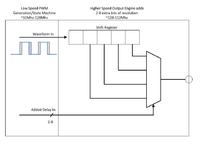
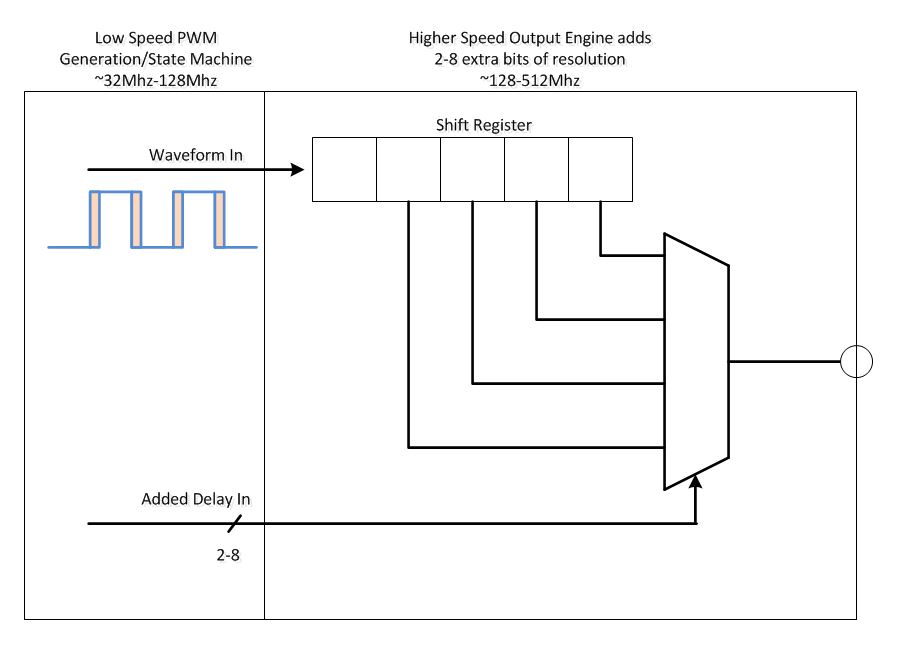
The point is that the middle stage, the PWM/State Machine running at ~32-128MHz will generate the overall output PWM while also perhaps adding some additional logic like variable dead time, fault handling etc. The middle stage really runs the show and the final stage, the point of this thread, will only be adding some additional bits of resolution on top of that.
This is my first idea where the middle stage PWM output routes through a high speed shift register. An additional 'delay' output from the middle stage determines how much extra delay gets added to the output before it reaches the pin.
The output engine here consists only of a shift register and an asynchronous mux which should be able to run near the limits of the fabric. The mux control lines will only change when the shift pipline is filled with all 0's or all 1's hence glitching here shouldn't cause a problem (helped by the extra flip-flop added at the beginning). A final flip-flop may also be added before the pin to minimize variations in routing delay (though with a small timing cost I assume).
So any thoughts or other suggestions on this implementation or suggestions for alternatives?
-What about adding a second layer of muxed flip-flops that are clocked at different phases (I.E. 0/180 or 0/90/180/270), for an extra 1 or 2 bits?
-Any other ideas I didn't think of, using serdes popped into my head though I don't actually have serdes on this part
-A counter implementation would work as well, and scale better, but I feel its extra complexity might minimize speed potential
My initial plan is to have an architecture like this:
Error Amp -> PWM/State Machine -> Final PWM output engine
The point is that the middle stage, the PWM/State Machine running at ~32-128MHz will generate the overall output PWM while also perhaps adding some additional logic like variable dead time, fault handling etc. The middle stage really runs the show and the final stage, the point of this thread, will only be adding some additional bits of resolution on top of that.
This is my first idea where the middle stage PWM output routes through a high speed shift register. An additional 'delay' output from the middle stage determines how much extra delay gets added to the output before it reaches the pin.
The output engine here consists only of a shift register and an asynchronous mux which should be able to run near the limits of the fabric. The mux control lines will only change when the shift pipline is filled with all 0's or all 1's hence glitching here shouldn't cause a problem (helped by the extra flip-flop added at the beginning). A final flip-flop may also be added before the pin to minimize variations in routing delay (though with a small timing cost I assume).
So any thoughts or other suggestions on this implementation or suggestions for alternatives?
-What about adding a second layer of muxed flip-flops that are clocked at different phases (I.E. 0/180 or 0/90/180/270), for an extra 1 or 2 bits?
-Any other ideas I didn't think of, using serdes popped into my head though I don't actually have serdes on this part
-A counter implementation would work as well, and scale better, but I feel its extra complexity might minimize speed potential