Continue to Site

Welcome to EDAboard.com

Welcome to our site! EDAboard.com is an international Electronics Discussion Forum focused on EDA software, circuits, schematics, books, theory, papers, asic, pld, 8051, DSP, Network, RF, Analog Design, PCB, Service Manuals... and a whole lot more! To participate you need to register. Registration is free. Click here to register now.

Matching impedance 800ohm from audio line output etc...

Status
Not open for further replies.
Hi ,

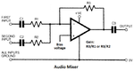
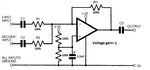
Can anyone of you provide me with a schematic of mixing two audio signals with an op amp like this "Analog Devices OP293FSZ" or like this "Analog Devices AD8656ARZ" ???

And a bit explanation of how i have to chose resistor values to not have a gain on the signals , just mixing them without the feedback problem i had when mixed pasive :)

Any help welcome

Warm regards
 

The OP293 is very noisy (audio hiss) and has a poor high frequency response. It also has a low output current. Don't use it.
The AD8656 is much better and is fine for audio. It has a low maximum supply voltage.

A mixer opamp is inverting. It has an input resistor and a feedback resistor. It can have many input resistors that do not affect each other. The gain is simply the ratio of the feedback resistor value divided by the input resistor value when driven from a fairly low impedance source. When the resistor values are the same then the gain is 1 like a piece of wire.

Here is an audio mixer circuit:
 

Attachments

  • audio mixer.png
    audio mixer.png
    66.2 KB · Views: 92
Hi Audioguru ,

What is Bias voltage? , and what capacitors are used?

Am i correct that r3 and r1 and r2 must be the same for no gain?

Warm regards
 

The bias voltage is a reference voltage for the opamp that is usually half the supply voltage so the output can swing equally up and down. If the power supply is positive and negative then half the supply voltage is 0V which is ground.

If R3 is 100k and R1 or R2 is also 100k then the gain of that input is 1. Of an input resistor is 10k then the gain of that input is 10.
 
So the bias voltage i have to do nothing with it , on some other schemes they put it to ground.... is this ok?

Also i have a question about inverting opamp....
Some schemes do invert ,others do not (positive to signal , negative to ground)

What's the reason , is it dependend of the used opamp or what you want to do with it?

Probably a 'stupid' question, but anyway i don't know :)

Warm regards
 

So the bias voltage i have to do nothing with it , on some other schemes they put it to ground.... is this ok?
If the bias voltage is not near half the supply voltage then the output cannot swing equally up and down and will be severely distorted (it will be rectified).
If the supply is +12V and -12V then what is the voltage of half the supply voltage? It is 0V which is ground. Then the output can swing up to about +11V and down to about -11V without any distortion.

Also i have a question about inverting opamp....
Some schemes do invert ,others do not (positive to signal , negative to ground)

What's the reason , is it dependend of the used opamp or what you want to do with it?
An opamp has a voltage gain of 50 thousand to millions at DC and low frequencies without negative feedback. Negative feedback reduces the gain, reduces distortion and makes the output an extremely low impedance.
The (-) input of an opamp always has negative feedback from its output and is never at ground.
When an opamp is in an inverting circuit then input resistors can be added and the inputs do not affect each other making an excellent mixer.
But when an opamp is in a non-inverting circuit its input has a very high resistance so if more than one input is connected then the signal from one input can go to and cancel or mix with another input signal at the source of that signal.
 
The bias voltage is a reference voltage for the opamp that is usually half the supply voltage so the output can swing equally up and down. If the power supply is positive and negative then half the supply voltage is 0V which is ground.

If R3 is 100k and R1 or R2 is also 100k then the gain of that input is 1. Of an input resistor is 10k then the gain of that input is 10.

In this case the supply voltage is +3V to +5V , what does this mean for this bias voltage then?
 

The bias voltage should be half of the supply voltage. Then use two same-value resistors in series across the supply and ground and their junction is the bias voltage that can have a capacitor to ground as a filter.
 

Attachments

  • opamp mixer 2.png
    opamp mixer 2.png
    74.2 KB · Views: 93
  • Like
Reactions: Zaaappp

    Zaaappp

    Points: 2
    Helpful Answer Positive Rating
Don't understand much of it

Now +VE also must be grounded???

And what the value of C1 C2 C3?

I feel stupid :)
 

Very simplified explanation:

1. You ideally want the output pin to be at half the supply voltage so it has most 'reach' above and below it.
2. The op-amp likes to have both it's inputs at the same voltage.

So if you fix the '+' (non-inverting) input at half the supply voltage by connecting it to the middle of two equal value resistors between ground and supply, it's output pin will try to push current through R3 to make the '-' (inverting) input pin the same voltage.

Now, if you feed a signal through R1,C1 (or R2,C2) it will push the '-' input slightly higher or lower, the IC sees the inputs are no longer at the same voltage so it fights back to make them the same again by adjusting the output voltage and hence current through R3 to bring them back into balance again.

Now think of that signal at one of the inputs, you really don't want it to loop around and come back out through the other input, instead you want the combination of both inputs to appear at the output. In that circuit there will never be any coupling between them, the reason is that the '-' input is a virtual ground. To explain, it isn't real ground, there is no connection to the ground rail but it will always have zero signal on it so it behaves like real ground in that respect.

At first it may seem crazy that your amplifier has no signal at it's input but the output carries an amplified version of it. Stop and think though, the IC is doing it's best to keep those input pins at the same voltage and you are not applying any signal to the '+' input so it will push current through R3 to counteract any signal you apply to it's '-' input. If the signal you apply meets it's exact opposite coming through R3, the result will be zero, they cancel out (= virtual ground), BUT to do that, the other end of R3 has to carry the combination of both signals and that's what you use as your output.

The capacitor values have no effect on the operation of the circuit except to limit the gain at low frequencies. A capacitor blocks DC so it doesn't upset the working conditions of the IC but to an AC signal it looks like another resistor, lets call it's value Xc. The value can be calculated at any frequency with the formula:
Xc = 1/(2 * pi * f * C) where the units are Xc in Ohms, f in Hz and C in Farads.

C1 and C2 are already in series with large value resistors so unless their Xc was also large, they would have little effect on the LF response. For example the frequency at which the signal dropped to half voltage if their value was 1uF would be 0.795Hz, (well below hearing range) because Xc would also be 200K, doubling the effective resistance in series with the input.

The same formula applies to C3 but to calculate how much it influences the low frequencies it is necessary to know what load is connected at the output. A typical value would be 10uF for audio applications.

Brian.
 
Ok ... i understand a bit more

Is there anything changing if i would use a +12V of +9V ?

Because maybe i use an opamp that has this input voltage instead (it goes better in my total cirtuit)

Warm regards

- - - Updated - - -

And yet another question...
What about the polarity of the capacitors?

I only have polarized ones

Warm regards
 

The power supply voltage of an opamp is not its input voltage. You suggested the opamp AD8656ARZ that shows an absolute maximum allowed supply voltage of 5.5V and all spec's are shown with a supply of 5V on its datasheet. If you use a supply of 9V or 12V then that opamp will be destroyed. Many other good audio opamps work from a supply voltage as high as 36V.

An OPA134 audio opamp works from a supply that is from 5V to 36V.
 
  • Like
Reactions: Zaaappp

    Zaaappp

    Points: 2
    Helpful Answer Positive Rating
The power supply voltage of an opamp is not its input voltage. You suggested the opamp AD8656ARZ that shows an absolute maximum allowed supply voltage of 5.5V and all spec's are shown with a supply of 5V on its datasheet. If you use a supply of 9V or 12V then that opamp will be destroyed. Many other good audio opamps work from a supply voltage as high as 36V.

An OPA134 audio opamp works from a supply that is from 5V to 36V.

Yes i know:)

But now i have changed my mind and will use another opamp that works from a supply of 5 to 36V :)
That's why i asked if it changes any of the values in the scheme if I use that :)

Warm regards
 

The 100k resistor values are high enough that an opamp will not be overloaded by driving them when the output level is very high.
 

The 100k resistor values are high enough that an opamp will not be overloaded by driving them when the output level is very high.

In fact i wanted to use 10K ohm resistors and an opamp that has a power supply voltage of +9V or +12V


Warm regards
 

As long as the op-amp is specified to work from the voltage you supply it, there should be no problems. The important thng is the two resistors at the '+' input should be the same value so the center point is half the full supply line voltage. To be honest, there isn't much point in reducing any of the values although it wouldn't cause any problems. If you make the values too low (less than about 10K) all you do is waste current and make the op-amp work harder, the output wouldn't change. Lower values also place more load on whatever is feeding the amplifier inputs.

Brian.
 
If you reduce the value of the input resistors 10 times then for the low frequency response to be the same with resistor values 10 times less then the value of the coupling capacitors must be 10 times more.
 
And what about using polarized capacitors?
How must i translate the scheme , how must i integrate the polarity of these capacitors?

Warm regards
 

The rules regarding polarity are simply that the '+' end of the component goes to the more positive point on the circuit. To some degree that means you need to know whether there is already any voltage at the input source and also whether the stage following the circuit has a voltage already at it's input.

As I explained earlier, the '-' input of the amplifier will be at the same voltage as the '+' input due to the feedback resistor so it should be at half the supply voltage. So for example, if your supply is 12V, there would be 6V at the '-' input and you would orientate the capacitor according to whether that was higher or lower than the voltage from the source. The output pin would also be at 6V so you can work out if that is higher or lower than present at the input of the circuit following it.

Brian.
 
Well ok .. that makes it more complex for me :)

Another question , i just got my opamps delivered (texas instruments)
I got one soldered on a dedicated board :) yieepiee
And i do not know where pin 1 is :-(

I included how the opamp looks like (no indication of pin one that i know of) and the opamp description from TI with a mark to pin one

So maybe someone can figure out ?


Status
Not open for further replies.

Part and Inventory Search

Welcome to EDABoard.com

Sponsor

Back
Top