Vermes
Advanced Member level 4

The aim of this device was to make a manipulating robot with five DOF of the gripper, which parameters allow operating on heavy objects placed about 1m away from the robot. The lightness of the construction is obtained thanks to the aluminum skeleton. There were also used DC motors with gearbox, torque and power which is greater then the servo modeling.
The assumptions:
- five degrees of freedom
- the gripper reach 1m
- rotating hinges
- cheap and light construction
- DC motors with gear reducers
- the gripper of dimensions that allow moving the cylindrical objects (for example 1l drink bottles) with an opportunity of adaptation of different objects manipulating
Firstly, the mechanic construction is illustrated. It consists of the drive system and the drive transmission. There is also an accurate description of construction pictures which were displayed in AutoCAD. The control system monitors each degree of freedom by a separate microcontroller, while the main microcontroller directs and monitors the work of other ones.
The mechanic project
a)
b)

c)
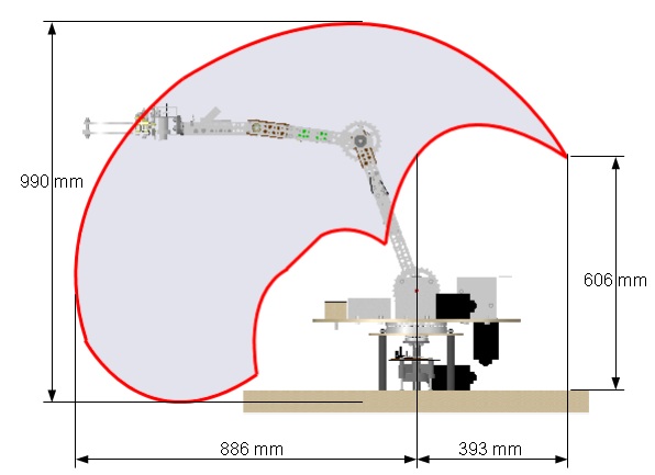
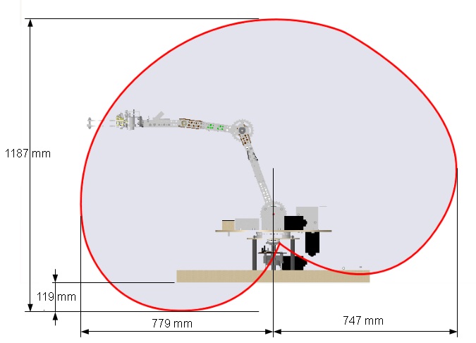
Fig. 2. The manipulator – workspace without the gripper: a) with a mobile wrist axis; b) the perpendicular position of the wrist relative to the base; c) at the parallel position of the wrist relative to the base.
In the figure 2, the manipulator workspace depending on the settings of the axis of the wrist-to-earth is displayed. Figure a) is an unnatural movement of the robot area. Only the constraints relative to each other at the same axis are taken into account, that means the angular constraints and the exclusion of the axis through collisions. Spaces of figure 2.b) and c) are natural workspaces. The first one shows the area of manipulation the objects grabbed from the top, while the second one - the area of manipulation in horizontal catching. The manipulator axis are limited by angles: the rotating axis 10-350 degrees, the shoulder axis 26-180 degrees, the elbow axis 14-343,5 degrees, the wrist axis 37,5-344 degrees and the gripper axis 10-350 degrees.
coś jest nie tak z tym rysunkiem, bo nie ma a,b,c
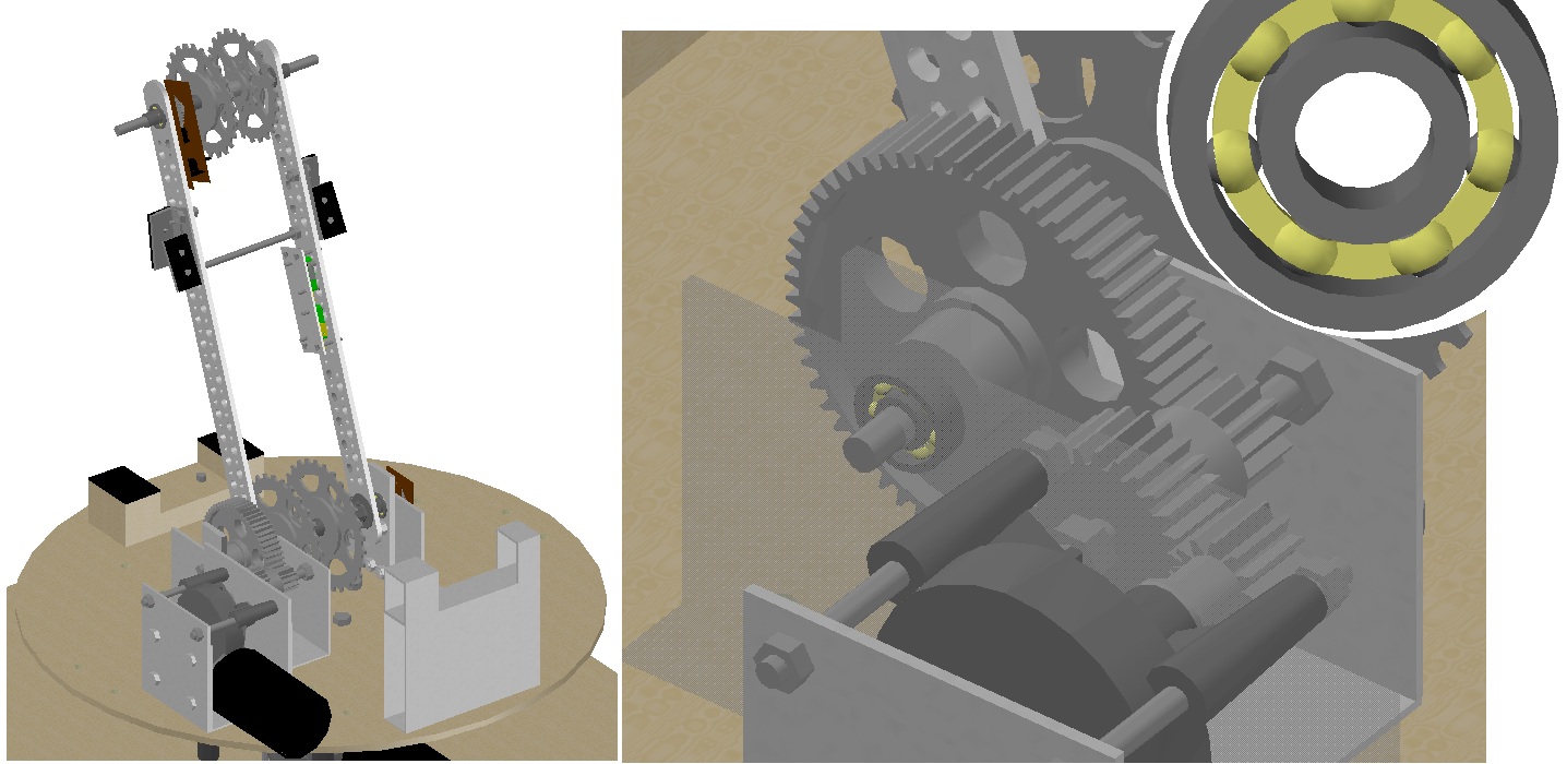
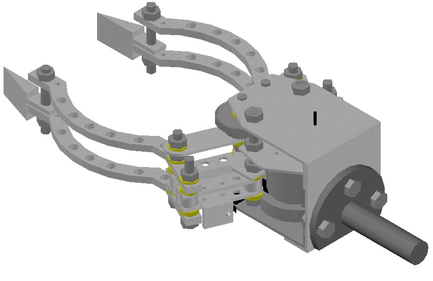
Fig. 3. The manipulator: a) view of the shoulder axis; b) close up on the bearings; c) bearing. Catcher is the most important part of the whole manipulator. Since it depends on what elements to be operated. The idea was to create the most universal gripper, but limited to the type of objects:
- cylidrical shape, e.g. bottles, glasses
- rectangular shape, e.g. blocks, boxes
- small objects, e.g. handkerchiefs, domino, chess pieces, pens
- object located low on the flat surface, what means those, whose height is small
- weight about 1,5 kg
a)
b)

Fig. 4. The gripper: a) general view; b) with an additional element
The manipulating robot is showed in pictures below.
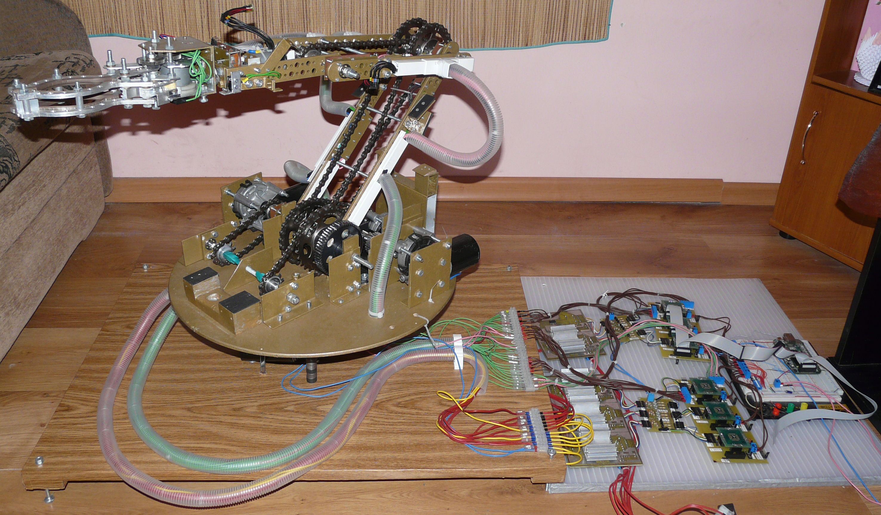
Fig. 5. The manipulator – a photo of the whole machine with the control system


Fig. 6. The manipulator – front and side.
The electronic and electric project of the control system
The system supporting manipulator is based on the standard control system. It consists of:
- executive module
- controller module drives
- the main module
- main PC
- remote PCs
- the auxiliary systems, i.e. the voltage converter
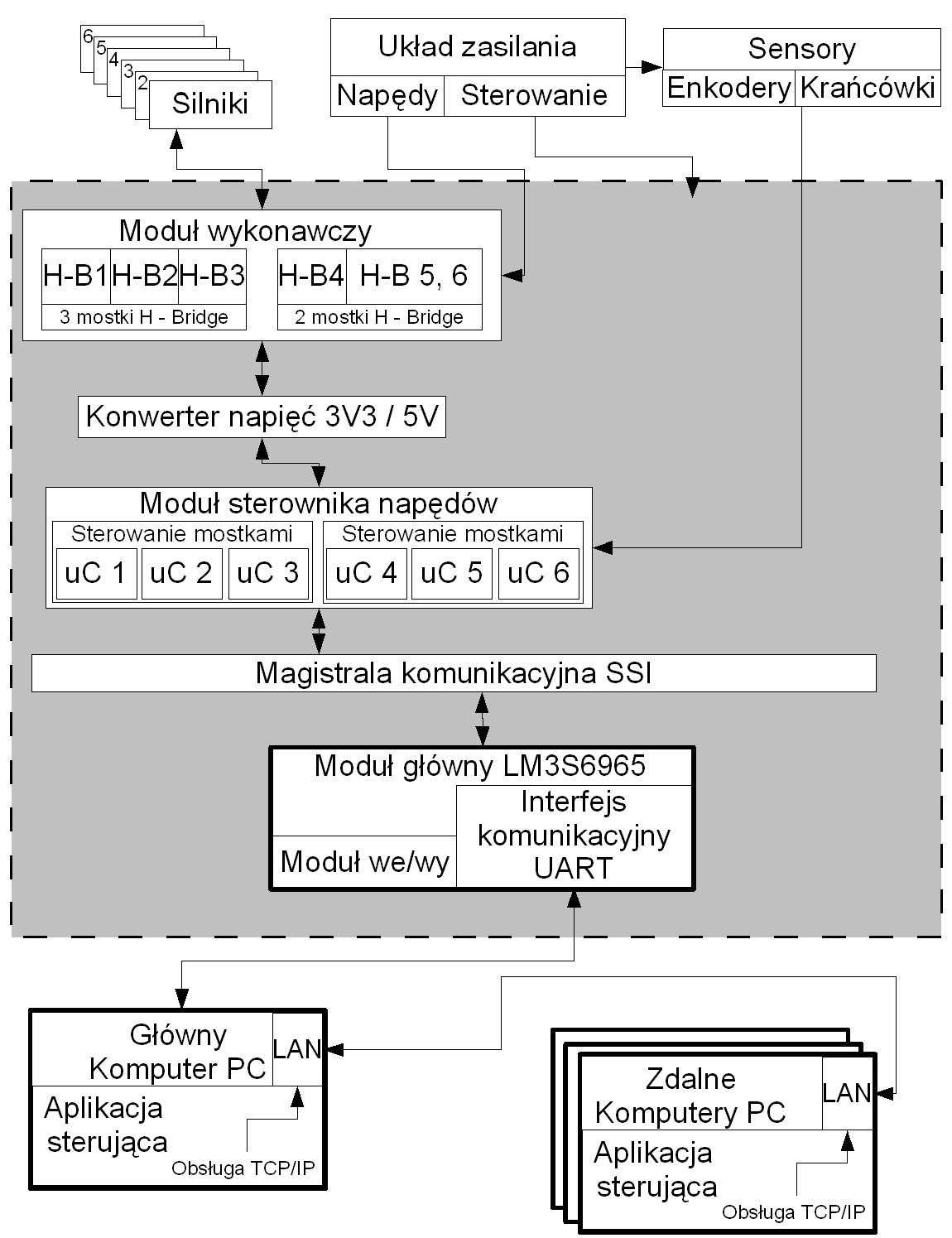
Fig. 7. The structure of the manipulator control system.
Four VNH3SP-30 H-Bridge and one double L293DD bridge are responsible for the motors control. They are parts of the executive module. The circuit boards are designed so that the heat generated is moving out. Additionally, the bridges are cooled using the heat sinks attached to them.
The bridges are controlled by LM3S818 microcontrollers, each one to one motor. A separate microcontroller is responsible for one axis then. That is why high computing power with the use of complex geometric calculations is reached. The drive controller module is divined into two plates of three microcontrollers each. These microcontrollers in addition to the adjustment of limit switches receive information, support two buttons for manual control of the axis. Circuit boards with microcontrolles have removed all the inputs/outputs to give the possibility of future expansion of the system.
The main control system of the rest microcontrollers is (płytka rozwojowa) with Cortex M3 LM3S6965. The picture below shows the whole electronic system based on the project.
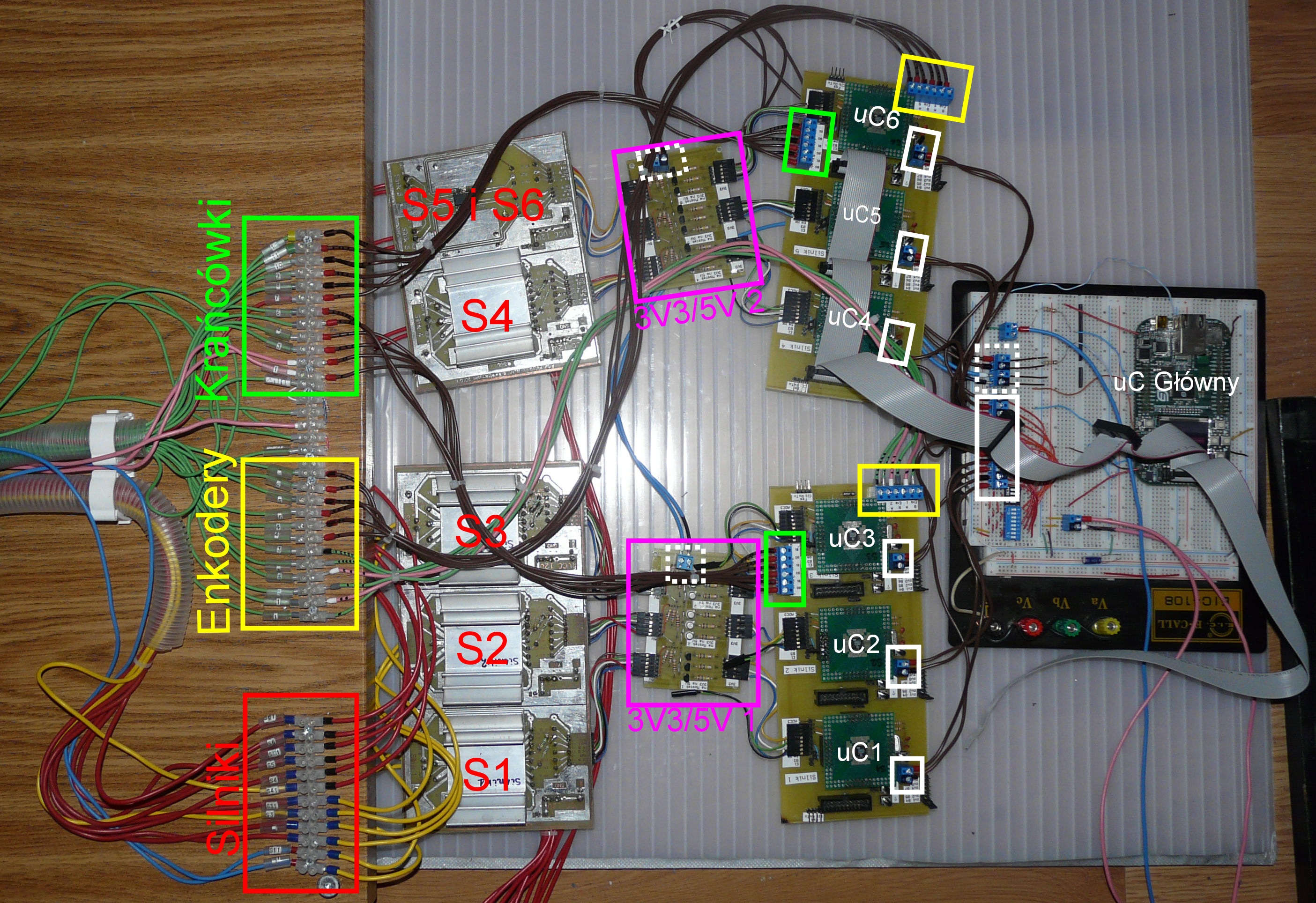
Fig. 8. Physically carried out the electronics.
Software control
Programs implemented for the microcontrollers were written in Keil uVision3. The main microcontroller LM3S6965 application was written to control six other LM3S818 systems. The main tasks performed by it are:
- receiving and sending data from/to PC via UART and their analysis
- management, receiving and distributing the information to SSI bus and their analysis
- supervision over the functioning of the entire machine
- viewing the key information on the display
Six LM3S818 microcontrollers are responsible for one of six axis. Their tasks are:
- sending and receiving information from the SSI bus
- receiving information on the state of two limit switches
- receiving information from two buttons
- control, overseeing the work of the H-Bridge motor connected to the main unit and information about its failures
- receiving information about the speed and axis position
The control application is written in Delphi 7. Its main functions are:
- control in Cartesian and spherical system
- graphical visualization of the machine state (side, top and gripper view)
- creating, reading and writing the automaton sequence
- connection to the microcontroller through the COM port
- application connections to each other with the possibility of chat and remotely controlling the machine
- supporting its own scripting language with syntax modeled on Delphi and C language
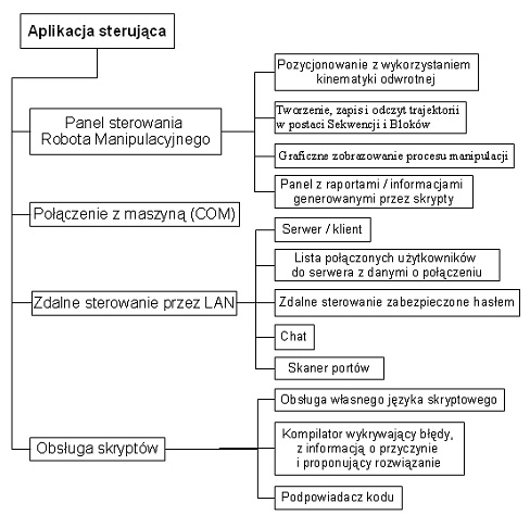
Fig. 9. Block diagram of the control application.
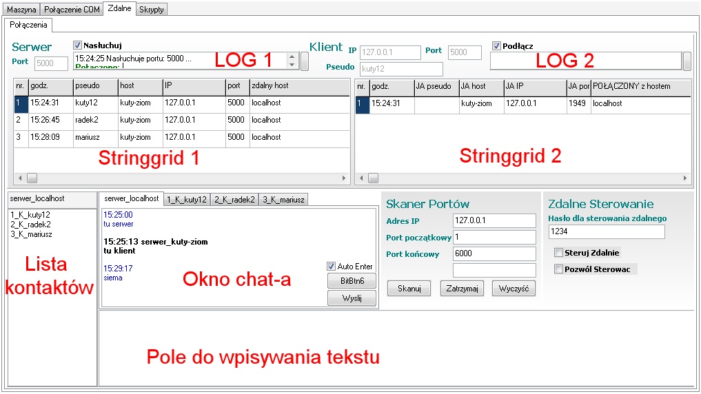
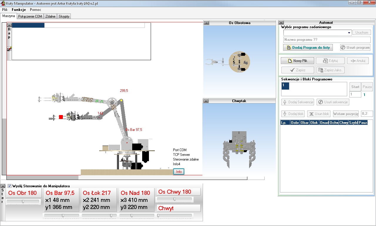
Fig. 10. The manipulator – view of the main program frame - “The Machine” and remote control.
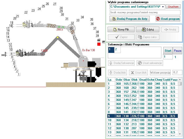
Fig. 11. The manipulator - “Automatic” panel and the gripper with set of points.
Link to original thread – Kuty Manipulator - Robot manipulacyjny o pięciu stopniach swobody z chwytakiem