Vermes
Advanced Member level 4

- Joined
- Aug 2, 2011
- Messages
- 1,163
- Helped
- 0
- Reputation
- 0
- Reaction score
- 0
- Trophy points
- 1,316
- Activity points
- 22,318
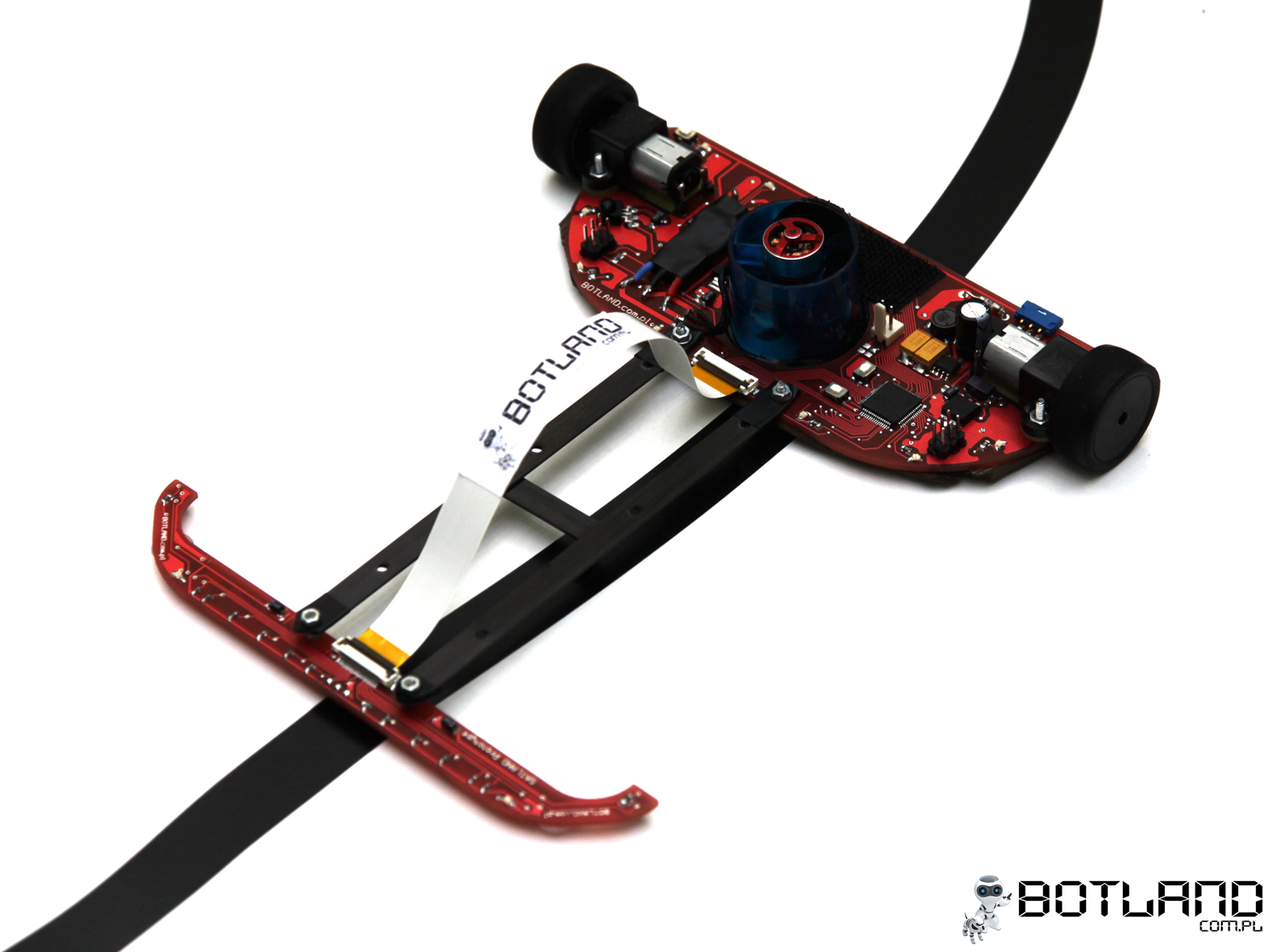
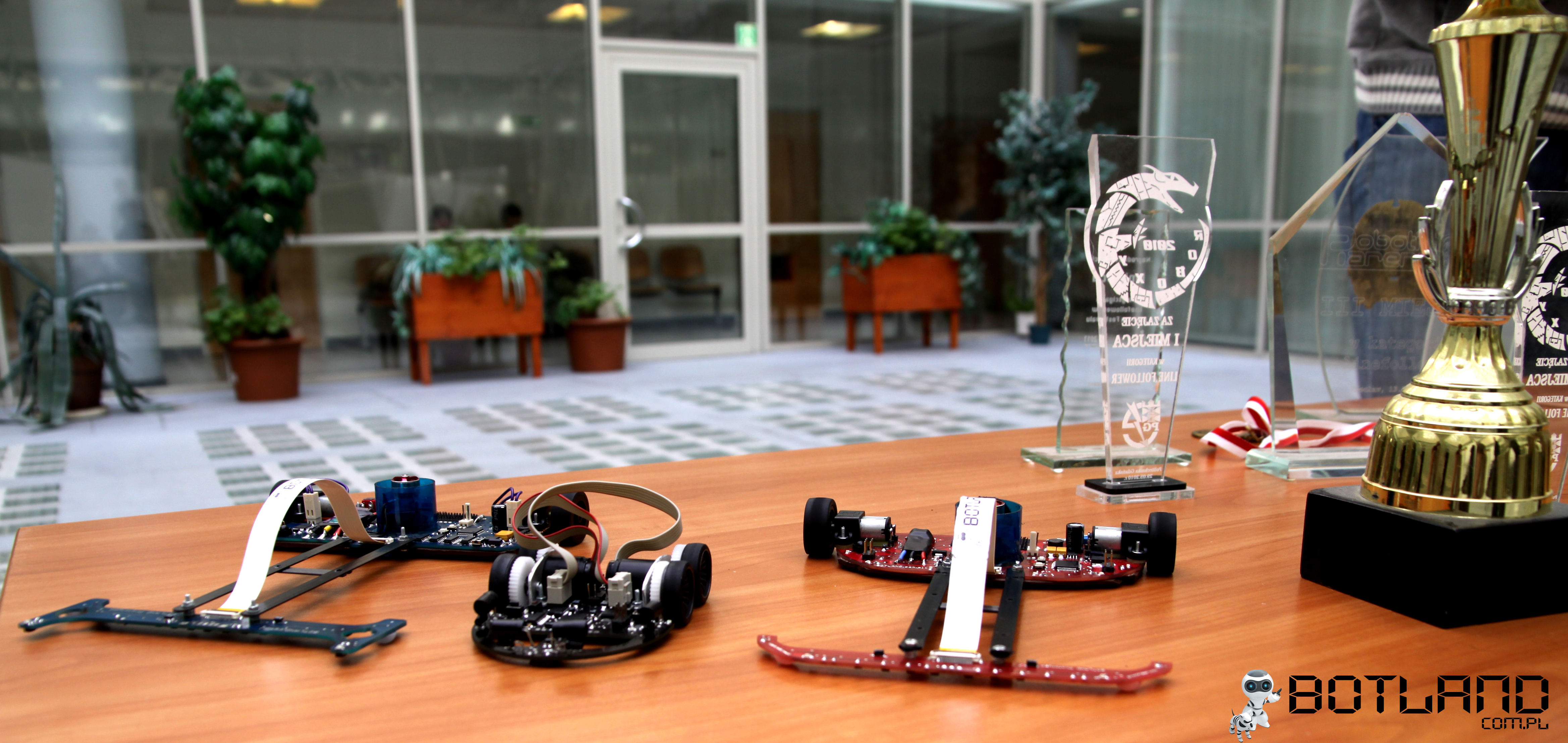
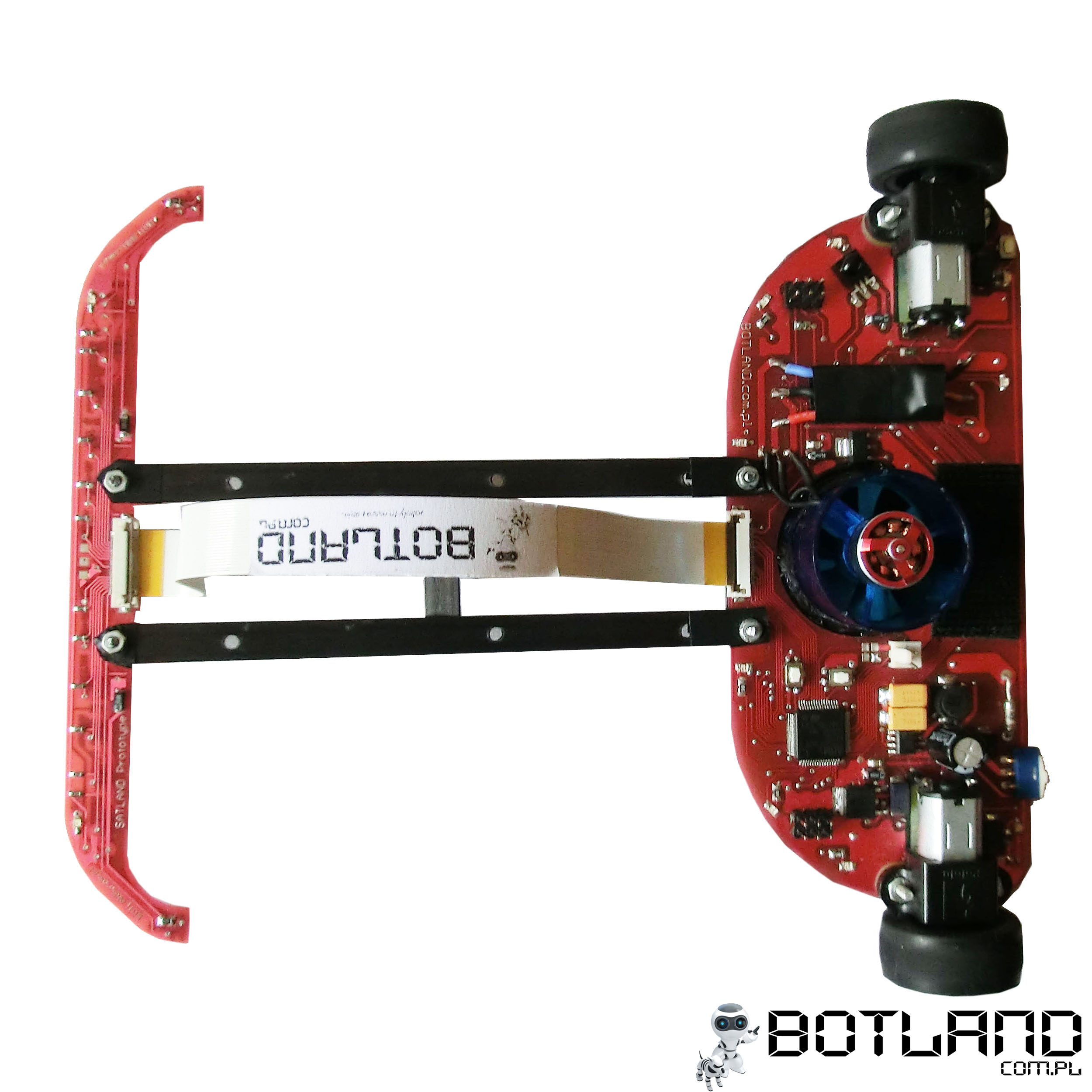
Presented here robot called Impact is a line follower of own construction. The robot won many competitions in Europe. It consists of two modules: main board and board with sensors, connected together by means of light carbon plates. The whole with accumulator weights only 105g.
Module with sensors:
It is the furthest element from the center of rotation. The moment of inertia is large (mass multiplied by the square of the distance from the center of rotation), so to be able to pull away sensors, weight of the board should be as small as possible.
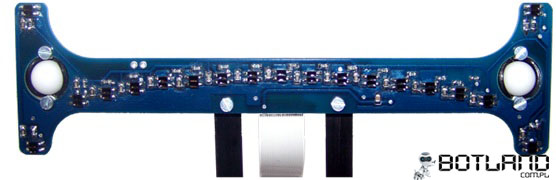
Picture below shows the previous version of the board with 19 sensors, 15 of which were arranged in an arc, 4 extended to the front and to the rear. The board was also equipped with comparators and a potentiometer to set the threshold value.
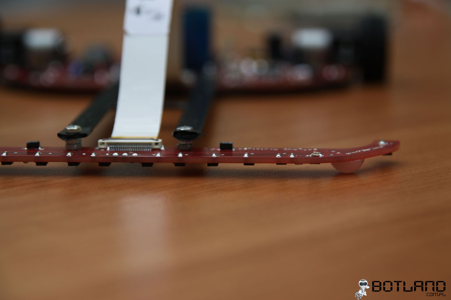
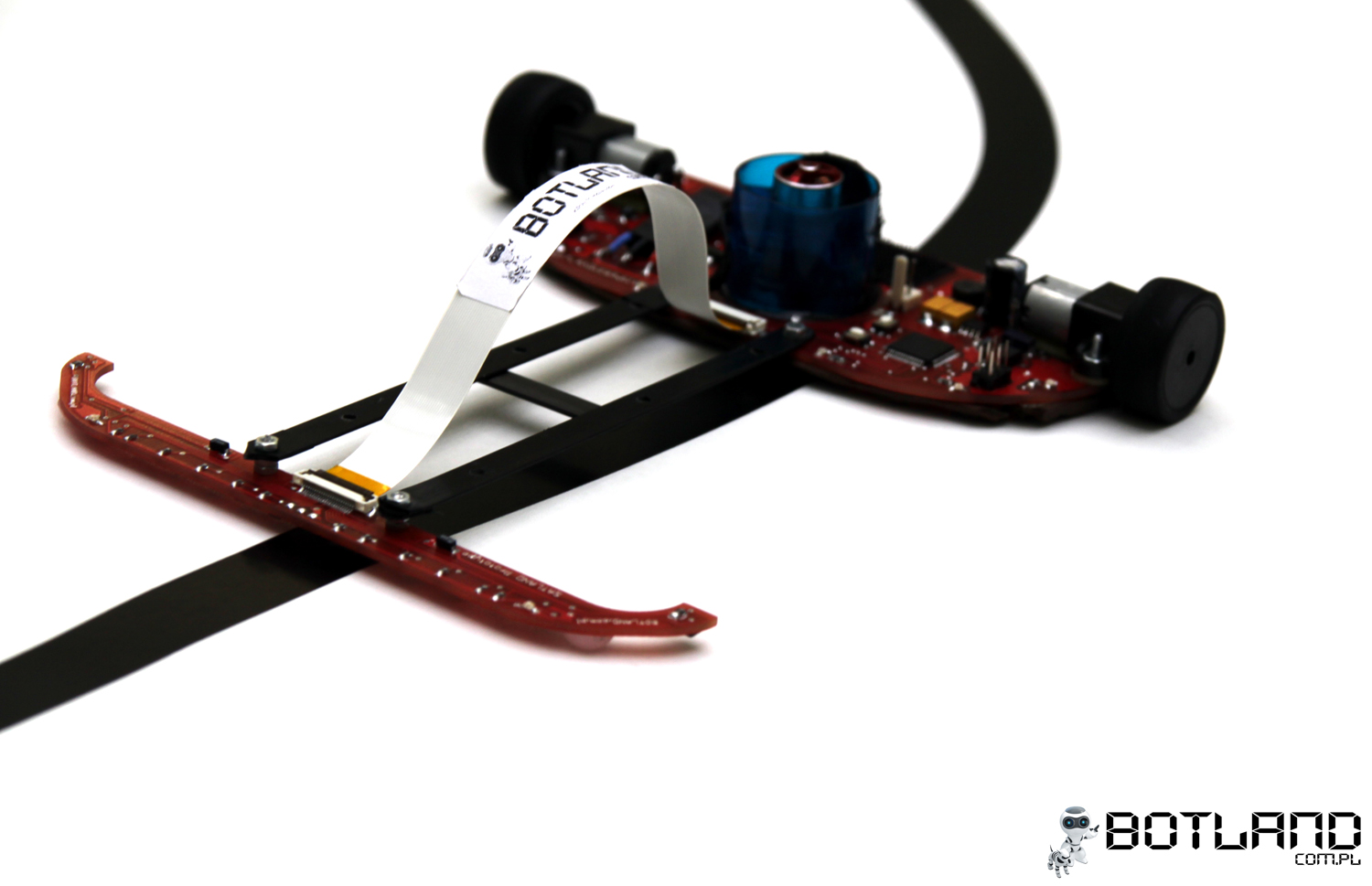
The new module uses 14 sensors arranged in greater distances form one another. Thus the range of first left and right sensors remained unchanged. In this version, there were no sensors pulled ahead. It turned out that at high speeds, taking into account the inertia of the actuator, the robot was not able to effectively respond to the signal derived from the sensors. Once the number of sensors was reduced, there was a possibility to use the built-in analog-digital converter in microcontroller (16 multiplexed inputs). That made it possible to resign from the comparators. Without these additional circuits, size of the board was reduced. The thickness of laminate could also be changed from 1,5mm to 0,8mm. These treatments resulted in a twofold reduction of the board weight from 8g to 4g. The module look is shown in the following picture:
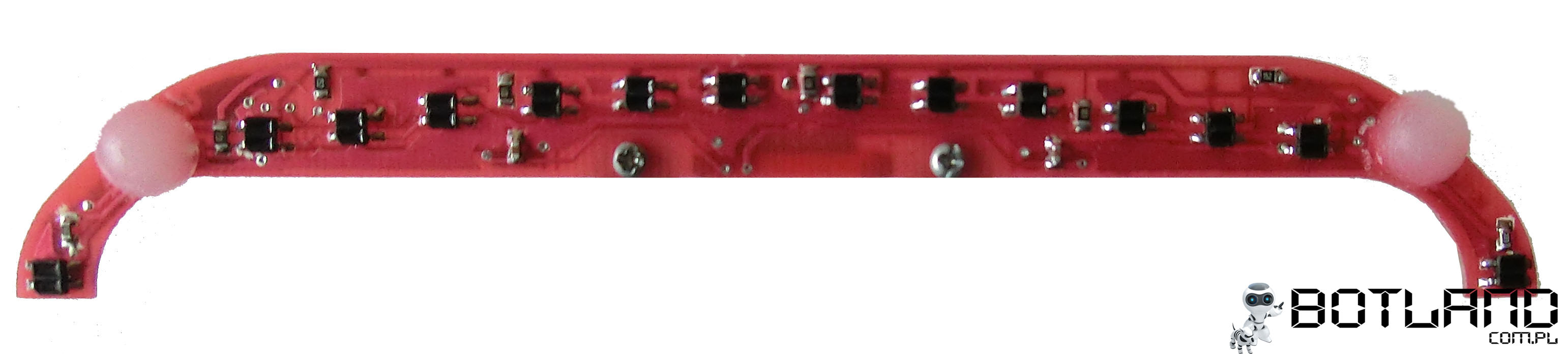
Lines are detected by means of reflective optocouplers KTIR0711S connected in series by three sensors with a resistor. There are also pads for the digital distance sensor Sharp 40cm.
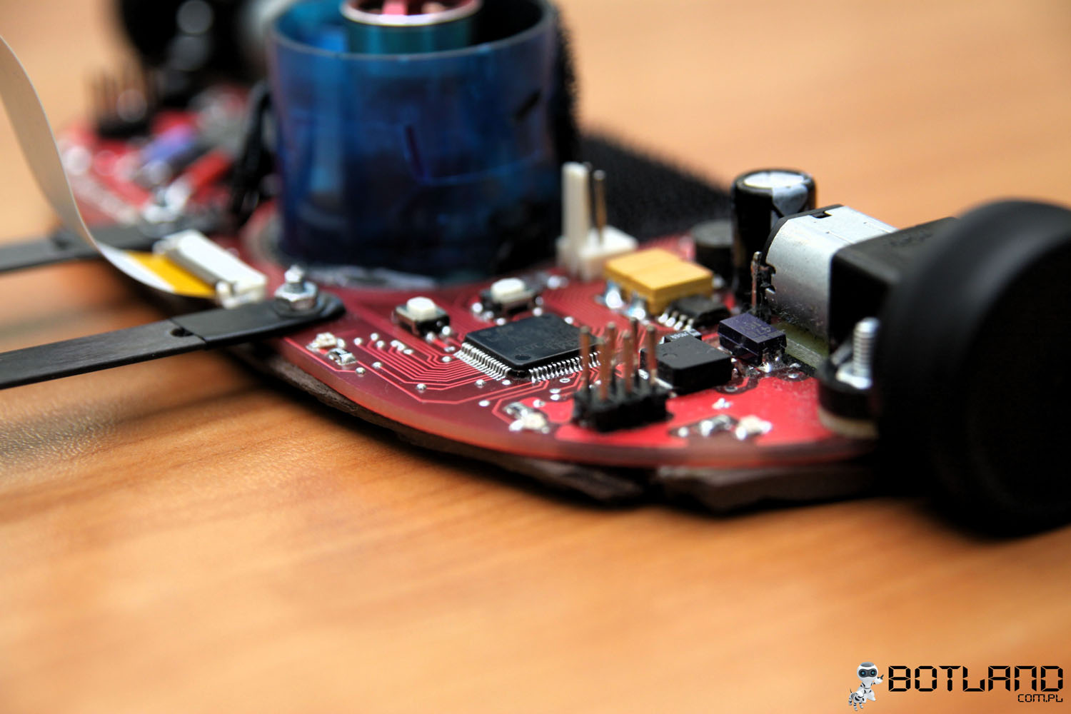
Main module:
The board is both the PCB and the underbody. Except the electronic circuits, it includes also drive engines and tunnel drive. The size of the module was significantly reduces in comparison to the previous version of the robot. Dimensions are: 140mm x 60mm.
Electronics:
The main element of the robot is mictocontroller STM32. Engines are controlled by H bridges TB6612. Supply consists of pulse converter 5V and linear stabilizer 3,3V.
Microcontroller – 32-bit STM32F103RBT6 with core from ARM Cortex-M3. Some of its features: 128kB of Flash memory, 20kB RAM, USB, CAN, UART, I2C, SPI, ADC, DAC in housing LQFP64. It fulfills the following tasks:
- read input ports states
- convert analog signal to digital
- generate PWM signal
- control over H bridges – generate adequate signals
- implementation of control algorithm
- communication with LCD module
- LED control
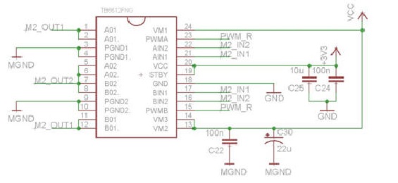
Engine drivers – two two-channel Toshiba H bridges TB6612, that allow:
- control over the rotation speed by means of PWM signal
- change the direction or engine rotations by changing states of two outputs
- rapid braking
To protect the circuit against damage when the maximum current is consumed by the engines (1600mA), channels A and B of bridges were combined (current efficiency raised to 2A). Bridges were connected as shown in the following picture:
Remote control:
Due to the achieved high speed while driving, it is difficult to stop the robot manually. Start and stop is carried out wirelessly, using the IR. Applied here Attiny13 is responsible for decoding the signal from the remote control that transmits in RC5 standard. Solution developed by Philips increases resistance to interferences of environment and creates an opportunity to use universal and available remotes. It is also easy to use other buttons on the remote control. The additional processor was used due to high requirements on the reliability of remote stop, for example in emergency situations.
Drive:
Drive consists of two engines Pololu HP with gearing 10:1 with the following parameters:
- rotations at idle with power 6V: 3000rpm
- current at idle (6V): 120mA
- peak current: 1600mA
- torque: 0,3kg*cm (29mNm)
- dimensions: 24 x 10 x 12mm
- weight: 10g
Wheels consist of rims turned of polyamid and specially selected tires. The rim tightly fits the motor shaft and is secured with cyanoacrylate glue.
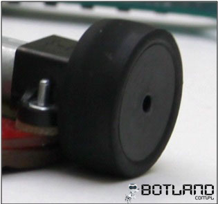
Tires selected for this robot were Mini-Z. They are 12mm wide and 3mm thick. Their hardness is equal 20° (in the range of 10°-60°). Tires with lower hardness are characterized by better adhesion, however, they wear out to quickly. Wheel and tire diameter is 27mm. The issue of tires cleanliness is also very important. Before each drive, they are cleaned in order to remove dust particles, which cause loss of adhesion and have a negative impact on performance.
Theoretically the maximum linear speed of the robot is approximately 3m/s. Depending on the route, average speed is 2,3-2,5m/s.
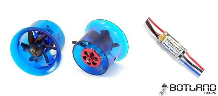
Tunnel drive:
An important element is EDF tunnel drive. It consists of a turbine (the same as in flying models, but inversely mounted). This element is to provide an additional pressure power that helps the robot stay on the road when cornering at high speeds (over 2m/s). The turbine is equipped with a brushless motor (11000rpm, power consumption about 4A), which is controlled by a driver from Dualsky.
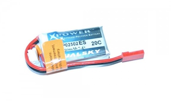
Supply:
The robot is supplied by Lit-Polymer Dualsky packet 220mAh, 25C, 7,4V. Constant current that can be ensured by the packet is 5,5A, while the peak current is 11A, and it is enough to proper supply. The accumulator allows for about 30 seconds of optimum drive, after that time the supply voltage drops, what negatively influences the dynamics and maximum speed of the robot. During the racing, the accumulators are changed every 2 drives and this allows to use the full power of motors. Such a small packet was used due to its low weight – about 16g.
Engines and tunnel drive are supplied directly from the accumulator. Electronic elements that require voltage 5V are powered by stabilized voltage by means of adjustable converter ST1S10PHR with current efficiency up to 3A. Processor supply (3,3V) is from linear circuit LDO (low-dropout) LF33CT, the output voltage of which is 5V from the inverter.
Supply schematic:

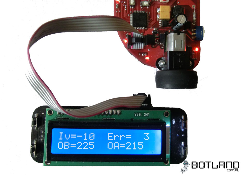
User interface:
Setting the regulator requires often changes of parameters such as: the maximum rotation speed of drive motors, turbine rotor speed or PID reinforcement. Connecting the robot to the computer after each passage, especially during racing where service positions are placed in some distance from the route, was very burdensome. In order to avoid this, a module with LCD was created, for viewing settings, equipped with buttons to control them. The weight is the key parameter, so that the circuit is a separate module that connects to the robot via UART interface.
Main features of the module:
- choice of controller settings
- choice of maximum speed
- choice of rotation speed of the tunnel drive turbine rotor
- check whether the operation of sensors is correct
- preview of the output data of the PID controller
- setting the threshold voltage for reflective sensors
Software:
Software was written in C using the libraries shared by STM: STM32F10x_StdPeriph_Lib_V3.5.0. Control algorithm is PID with some modifications.
Pictures:
Videos of the robot during racing:
Link to original thread - [Line Follower] Impact