Vermes
Advanced Member level 4

- Joined
- Aug 2, 2011
- Messages
- 1,163
- Helped
- 0
- Reputation
- 0
- Reaction score
- 0
- Trophy points
- 1,316
- Activity points
- 22,318
The Sun follower/tracking system is a kind of control system that allows the automatic or half-automatic tracking the Sun.
The main assumption of this design is implementation of a system tracking the Sun, the possibility to detect Sun and adequate controlling the DC engines so that the surface of solar receivers is set perpendicularly to the Sun rays. The device also has the possibility to measure temperature which is used to control the flow of heat sensor. It is also equipped with basic alarms with their configuration, LCD interface and four buttons. Program for this was made in AtmelStudio in C.
Hardware:
The design is based on 8bit microcontroller Atmega16P. It is powered as it was recommended in the note sheet.
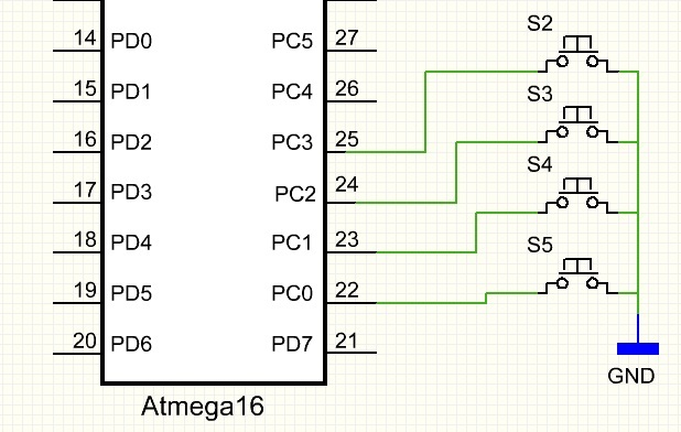
User's input interface was implemented using four popular monostable microswitches.

The switches handling was carried out on pins 0, 1, 2, 3 of port C. When pressed, the buttons short the pin of port C to the ground, thus giving the low state. At such a connection, input/output lines of pins 0, 1, 2, 3 of port C were configured as inputs with pull up to VCC. Oscillation of buttons are handled in software.
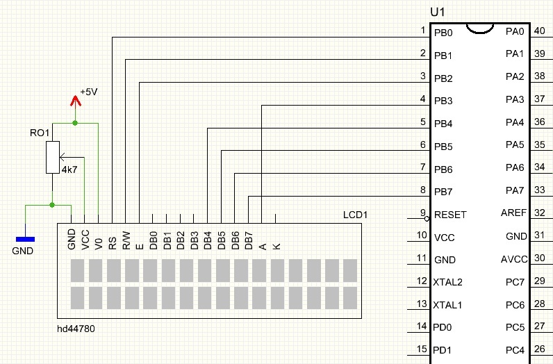
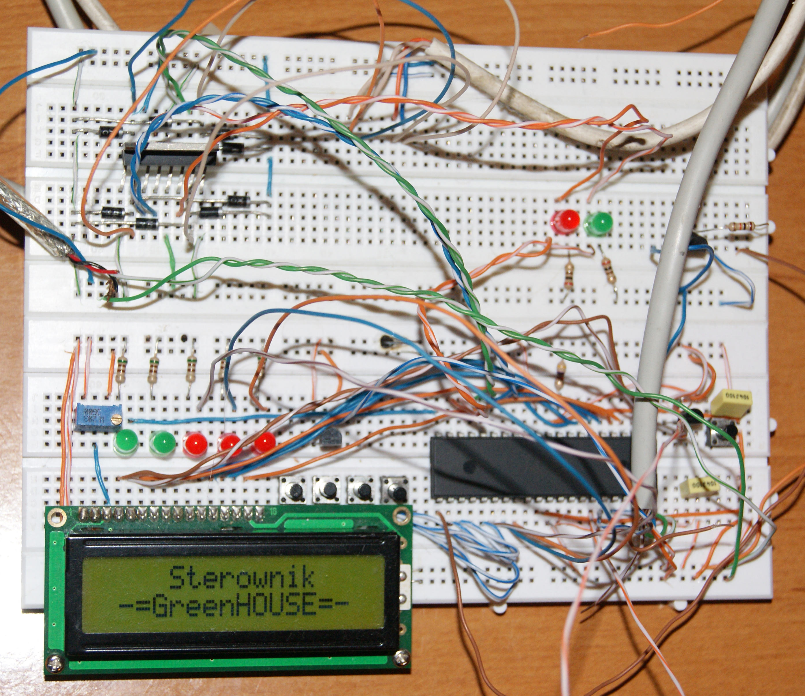
User's output interface was carried out using alphanumerical LCD display HD44780, connected to pins 0-7 of the port B.
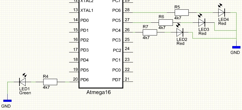
Electroluminescent LEDs are the visual, auxiliary indicator of the driver states. The LEDs handling was carried out with use of pins 6, 5 and 4 of port C and pin 6 of port D, which were configured as an output. If a high state is set on one of the pins, it will be indicated by lighting of the diode. Using the green LED1 indicates correct operation of the driver. When the diode is blinking with the frequency of 3Hz, the driver operation is correct, if the LED1 is lighting or it is turned out, it indicates that the driver is in suspension and it is necessary to implement reset. Red diodes: LED2, LED3 and LED4 are used for indication of active temperature alarms. If one of the alarms is activated, the corresponding diode will be lit.
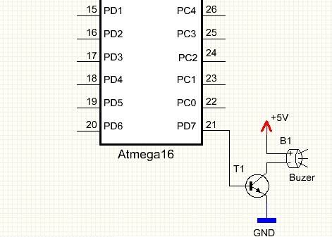
A buzzer with generator is the sound indicator of the driver states. The buzzer handling was carried out using pin 7 of port D, which was configured as an output. If there is a high state set on pin 7 of port D, that will generate the sound alarm. The buzzer can be used while handling the buttons – that setting can be enabled or disabled, each pressing the button can be additionally indicated by a short beep. Another function using that sound signal is signaling the active alarms. If one of the alarms is activated, it will be indicated by an intermittent signal.
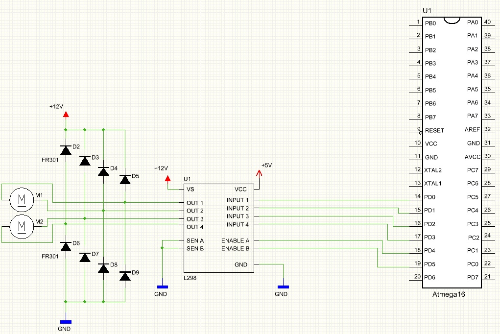
DC engines control system is based on L298 which implements two H bridge circuits. It can be powered from a constant voltage with a value less than 40V. It has four inputs using which it is possible to control two DC engines. Control can be carried out by setting a low or high state on one of the INPUT inputs.
The circuit is also equipped with ENABLE input for enabling or disabling one of the engines. Adequate setting the engine speed is carried out using a technique of modulation by width of PWM pulse. Two CURENT SENSING inputs connected to the ground are for the control of load current – when it exceeds 4A, the system will be disconnected. L298 handling was implemented using pins 0, 1, 2, 3, 4 and 5 of port D.
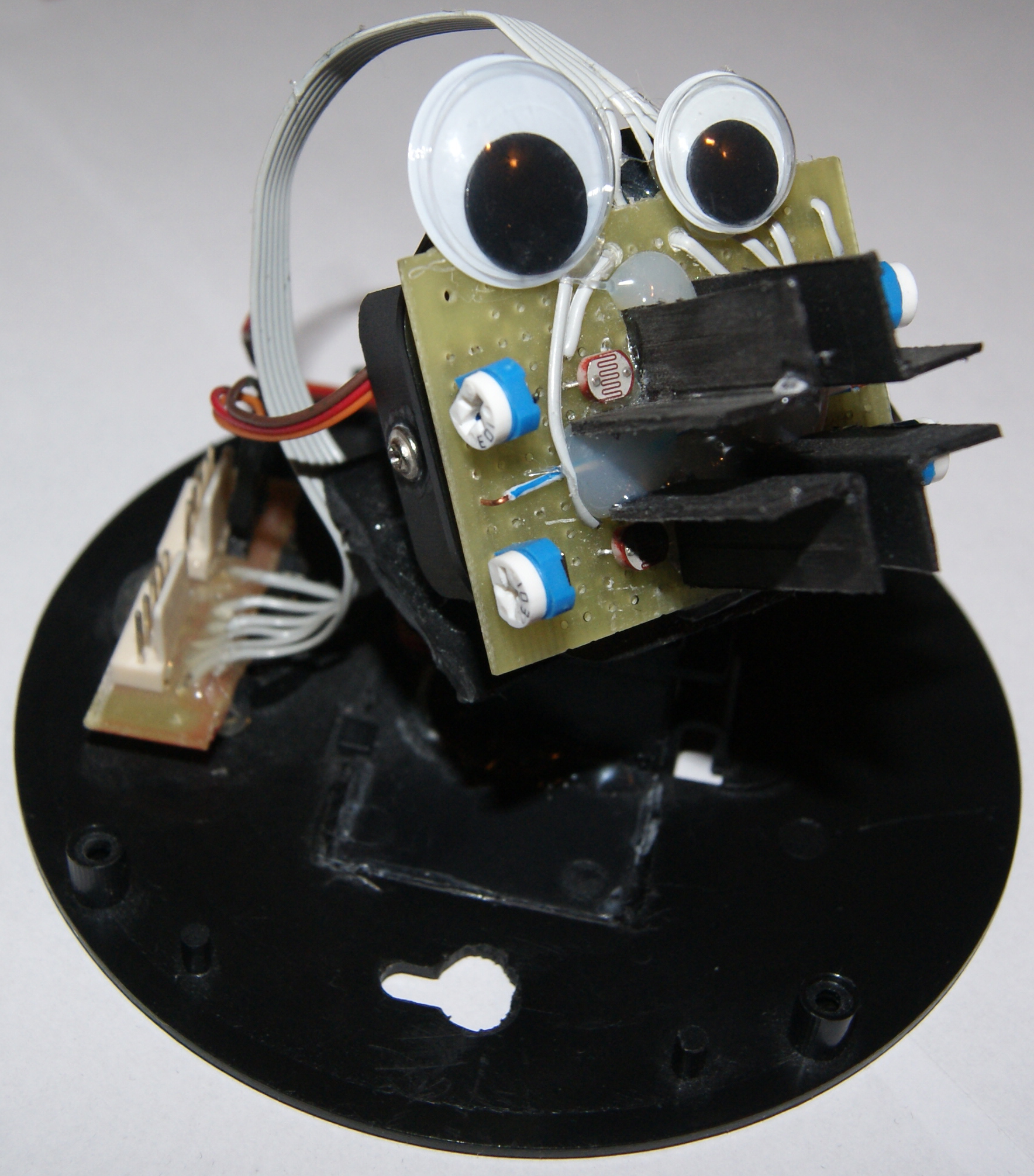
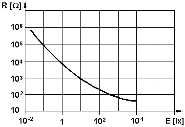
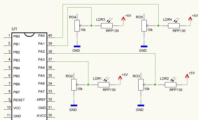
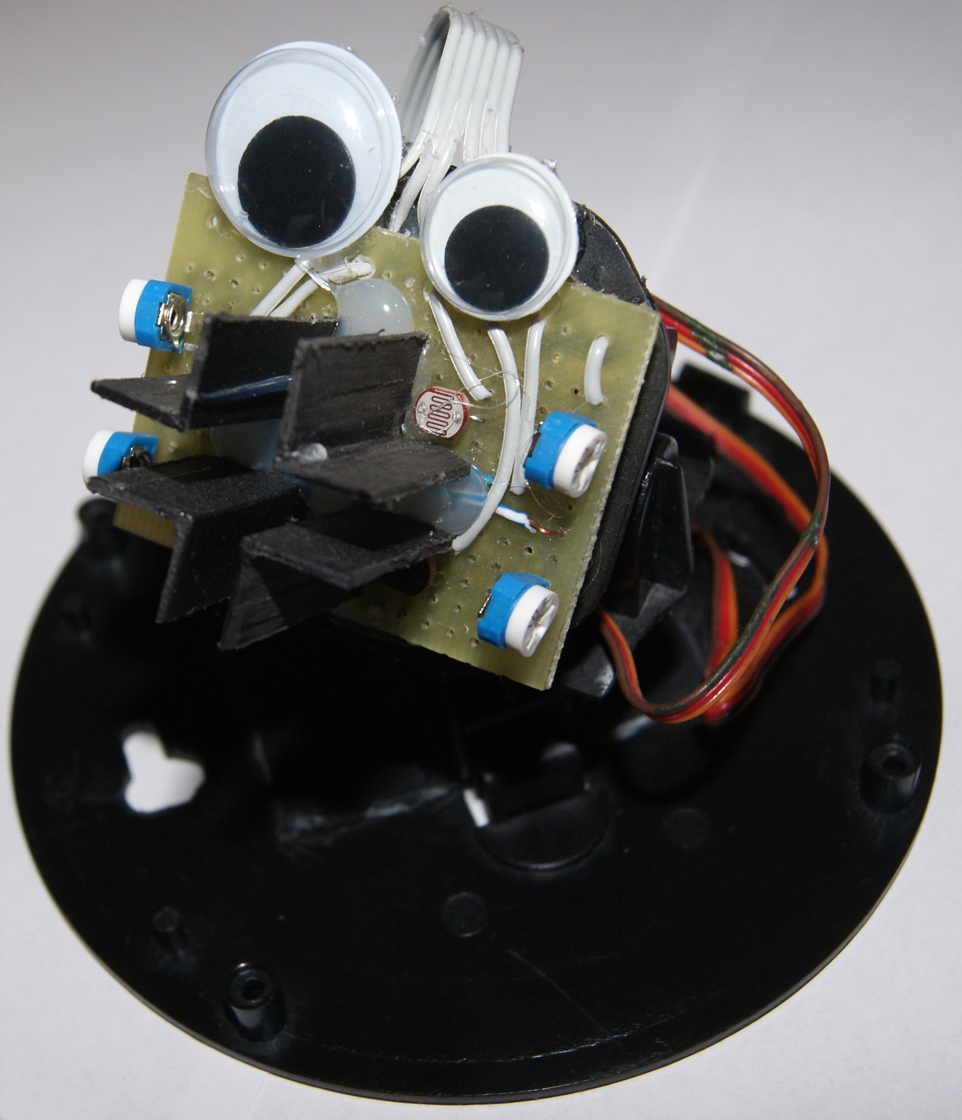
Measuring system of the light intensity was implemented on four sets of photoresistor RPP130 with adjusting potentiometer 10kohm, connected in a typical circuit of voltage divider. The photoresistor resistance is closely related to the intensity of light that falls on it and changes from the range of 1ohm to 10Mohm. The greater the light intensity, the smaller resistance of the photoresistor.
The potentiometer is used as adjusting resistor. It provides shifting the curve of Uwy (Uout) and R2, and thus – between Uwy and intensity of light falling on the photoresistor. Such built four sets of voltage divider are connected to analog-digital inputs of microcontroller Atmega16, where Uwy are connected correspondingly to pins 0, 1, 2, 3 of port A, and Uwe is equal 5V. At this connection, input/output lines of pins 0, 1, 2, 3 of port A were configured as 10-bit inputs of analog-digital converter.
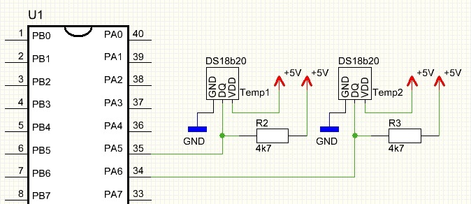
Temperature measure system uses pins 4 and 5 of port A and digital thermometer DS18B20 from Dallas. Chip DS18B20 is a digital sensor that communicates with the microcontroller using a popular 1-wire interface, then the microcontroller communicates with DS18B20 using only one I/O line.
Software:
Software uses a circuit that measures light intensity, control system of DC engines and adequate algorithm. The circuit measuring the light intensity and using the proper apertures makes it possible to determine in which planes with sensors it is, in relation to the source of light. If the source of light is not in the position perpendicular to the plane with sensors, apertures located in the plane cast a shadow on some sensors.
If the source of light is on the left, sensors located on the right are in shadow. Respectively, if the source of light is on the right, sensors located on the left are in shadow. If the source of light is on the bottom or top, corresponding pairs of sensors (upper or bottom) are in shadow. Uwy voltage measure allows to determine the location of source of light in relation to the plane on which the sensors are placed.
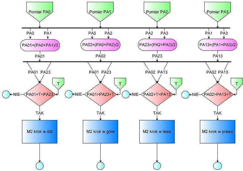
First of all, the results are grouped appropriately and arithmetic means are calculated. If the mean of two upper sensors (PA01) is less than the main of two bottom sensors (PA23), that means more light falls on the bottom sensors than the top ones. In addition, if the difference is greater than constant T (tolerance), L298 is used that by controlling the motor M2 moves the plane of solar receiver by 1-step down. Respectively, when these relations are inverse, the system that controls M2 moves the solar receiver plane by 1-step up. If the means are equal of the difference is less than the constant T, then the motor maintains its position. Analogical operation is carried out for means calculated by grouping sensors of the left (PA02) and right (PA13) side. If there is a difference in each of these cases and the difference is greater than the constant T, the motor moves the solar receiver plane – correspondingly – left or right. In that way, the function of solar follower is implemented. The process is repeated every 0,5s.
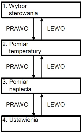
Menu – functions of the driver:
Menu of the driver is a multilevel one. Some of the functions are unavailable. You can navigate the menu using 4 microswitches: S2, S3, S4, S5.
- S2 “BACK” - move back to the level of the menu, variable edition disable
- S3 “LEFT” - navigate through the menu functions, change the variable by a unit down
- S4 “RIGHT” - navigate through the menu functions, change the variable by a unit up
- S5 “ENTER”- move forward to the level of the menu, variable edition disable
Turn on:
After turning on, the system calibrates within 2ms and default settings are uploaded, and the LCD displays the welcome screen.

The welcome screen is also the screen that is displayed in STAND_BY function. This function is self-activated when the driver is not used for 30 seconds, ie none of the buttons is used for 30 seconds, and after 40 seconds the LCD display light is turned out. If one of the buttons is pressed, STAND_BY function will be interrupted, and the driver switches to the main level of the menu. The main level of the menu consists of four positions, between which you can switch using buttons S3 “LEFT” and S4 “RIGHT”.
Descriptions:
- “Wybor sterowania” - choose the control
- “Pomiar temperatury” - temperature measure
- “Pomiar napiecia” - voltage measure
- “Ustawienia” - settings
- “PRAWO” - RIGHT
- “LEWO” - LEFT
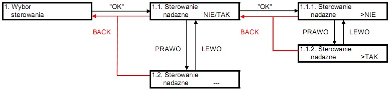
Choose the control:
In this box, the user can select one of two methods of solar receivers positioning. First of them is the following control and the other is time control. The driver does not have any RTC, and thus the selection of time control is not possible in this design, but you can improve your construction with that functionality.
Temperature measure:
In this box, the user can read the value of temperature measured by two sensors DS18B20 from Dallas and calibrate two types of temperature alarms.
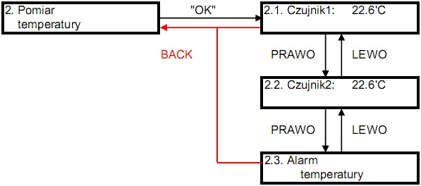
First type of temperature alarm can be determined for the first and/or second sensor. Setting the alarm can be done by setting the threshold for the measured temperature. If that value is exceeded for a sensor, the alarm is activated. The second type of alarm is determined for both sensors. Calibration of that type of alarm consists of setting the threshold, by which the measured value of temperature of the second sensor is greater than the measured value of temperature of the first sensor. If the difference between the temperature measured by the second sensor and the temperature measured by the first sensor is greater than the set threshold, the alarm will be activated.

Voltage measure:
Voltage measure is optional and it can be implemented instead of temperature measure depending on whether the driver is to be used with collectors or solar batteries.
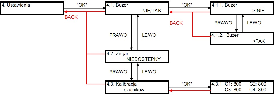
Settings:
Box of settings consists of three positions. First of them is used to enable or disable sound while buttons handling. The second one is to set the RTC (if it was assembled in the construction). The third one is to calibrate systems of voltage divider for determining the position of Sun in relation with the plane in which the photoresistors – sensors are placed. Calibration is setting the measure plane in perpendicular direction to falling Sun rays. Indications for all the sensors should be similar and their values should be about 800, and difference between the individual voltage divider systems should not exceed 50. Values measured in ADC are within <0; 1024>.
And there is a sample application of described above alarms for solar receiver (solar collector):
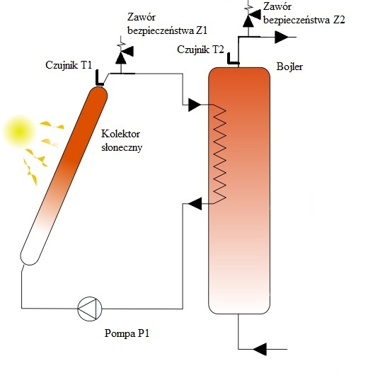
Sensor T1 is placed at the output of the solar collector. Sensor T2 is placed at the output of the boiler and then the alarms can be configured in the following way:
- Configuration ALARM1 – if water in the collector raises up to 100 degrees Celsius, the alarm and safety valve Z1 are activated.
- Configuration ALARM2 – if water in the boiler raises up to 100 degrees Celsius, the alarm and safety valve Z2 are activated.
- Configuration ALARM1-2 – if the difference of temperature between sensors T1 and T2 is greater than 50 degrees Celsius, that means for example an emergency of the pump forcing the circulation. The alarm and safety valve are activated.
Pictures of the prototype:
Measuring head was made of artificial camera with moving platform in an axis. Modeling servos were processed for DC motors.
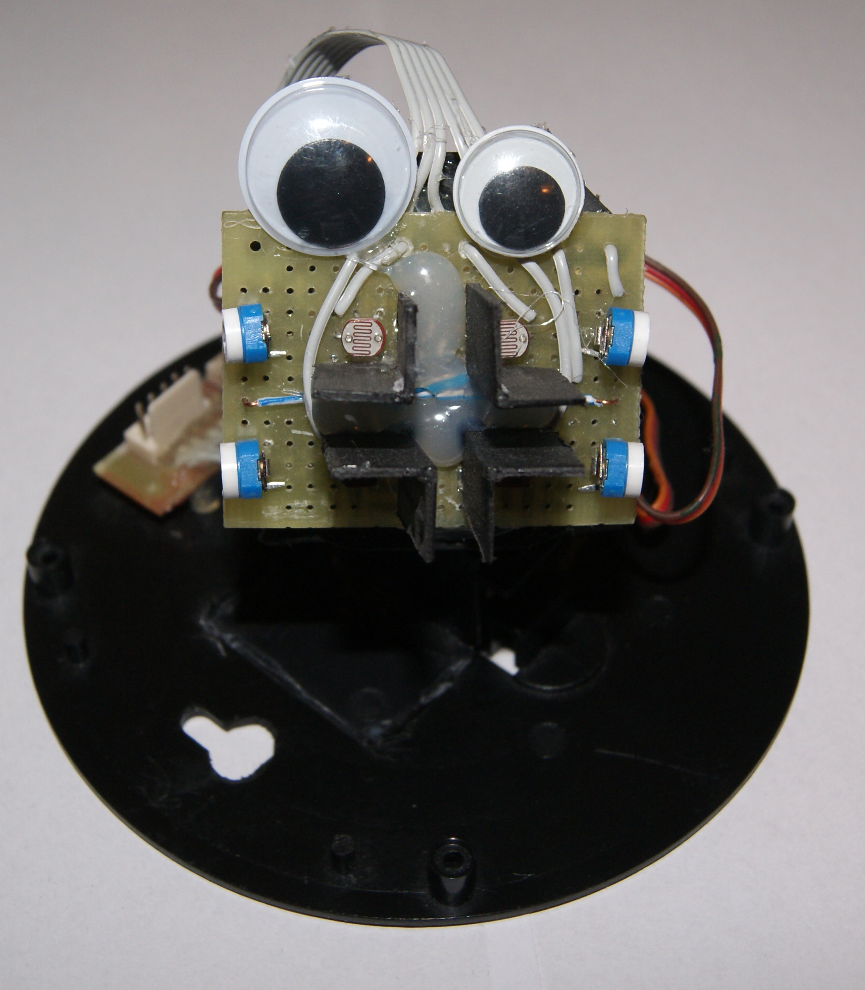
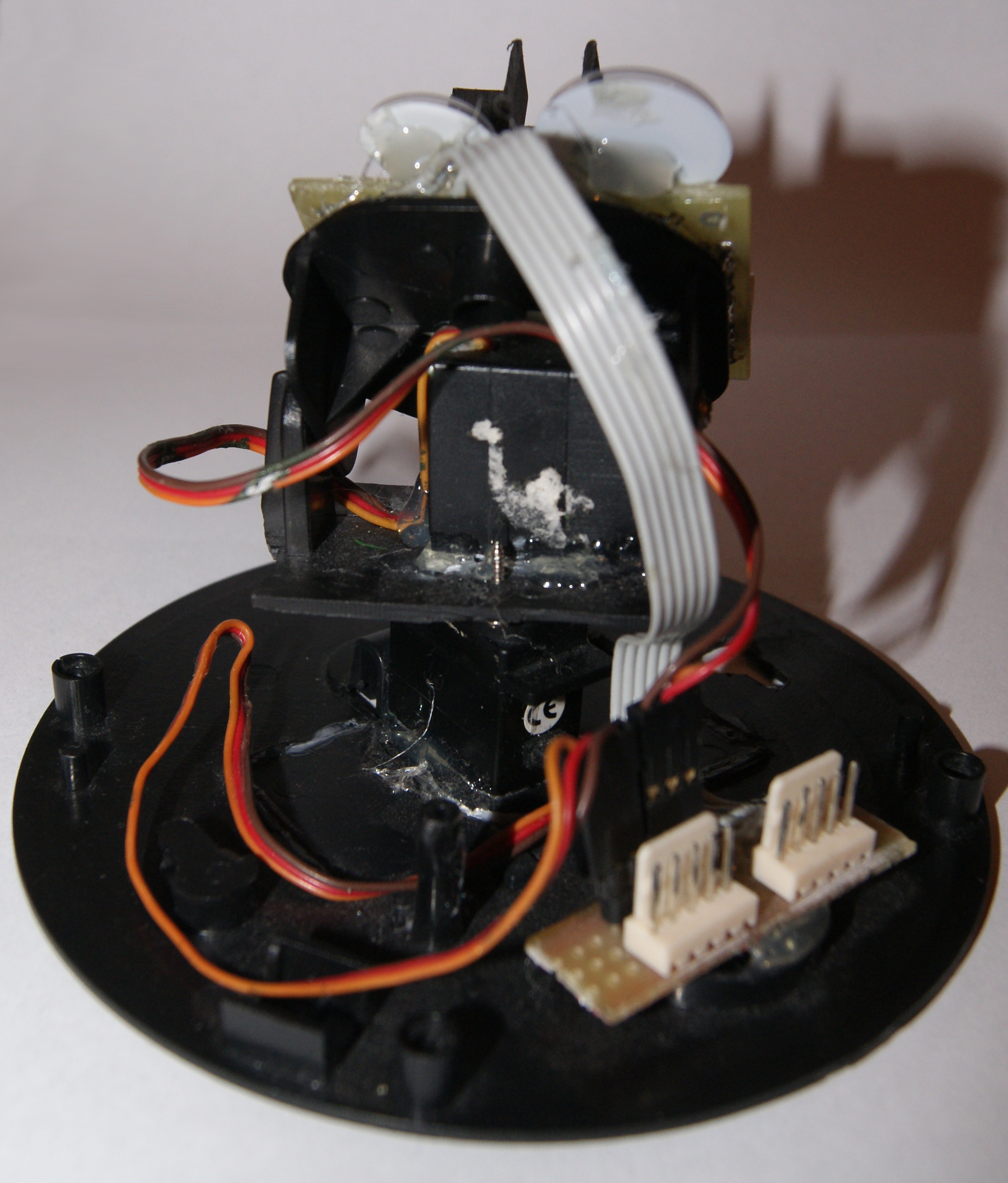
Calculating part with interface was made using a universal test board.
Video:
Link to original thread (useful attachment) - Układ nadążny za słońcem, ATMEGA16, LCD, ds18b20,L298, PWM, ADC