Continue to Site

Welcome to EDAboard.com

Welcome to our site! EDAboard.com is an international Electronics Discussion Forum focused on EDA software, circuits, schematics, books, theory, papers, asic, pld, 8051, DSP, Network, RF, Analog Design, PCB, Service Manuals... and a whole lot more! To participate you need to register. Registration is free. Click here to register now.

LTC2440 Problem: SDO Output Always Logic High

Status
Not open for further replies.

salihonur

Newbie level 5
Joined
Jul 13, 2011
Messages
9
Helped
0
Reputation
0
Reaction score
0
Trophy points
1,281
Activity points
1,383
Hi,
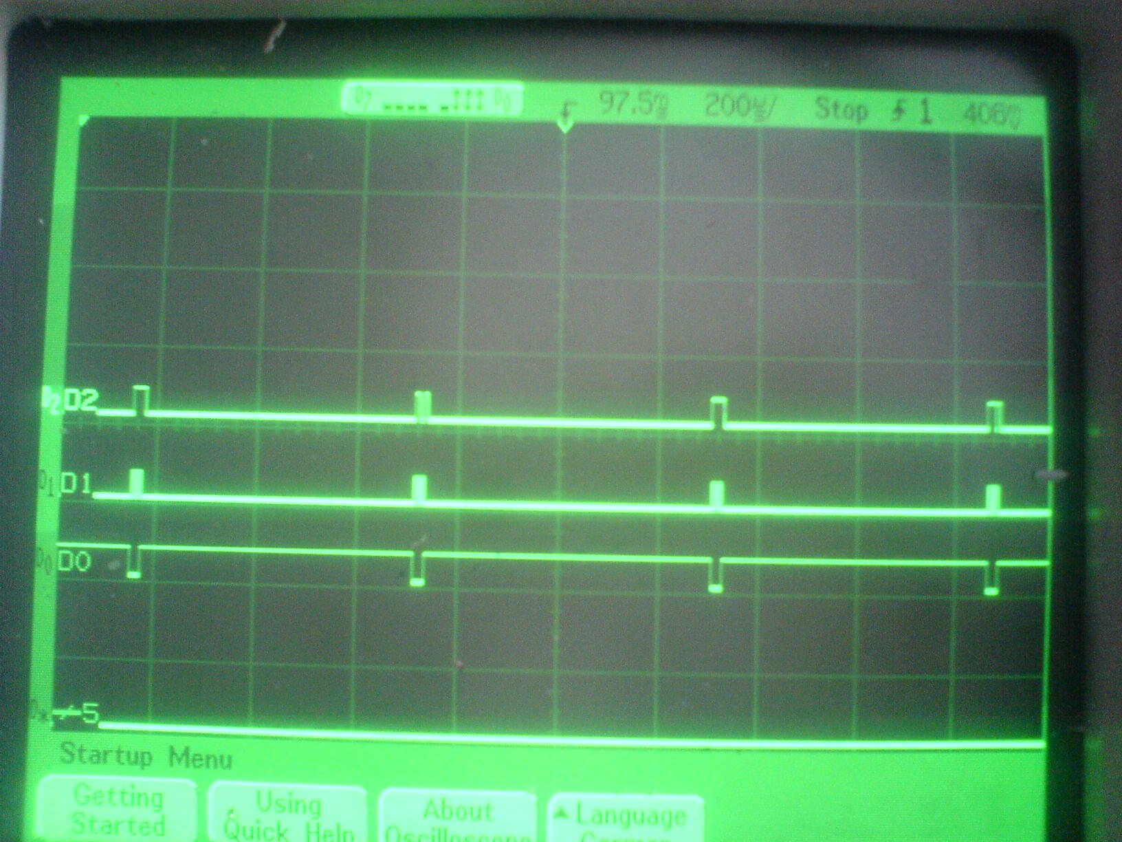
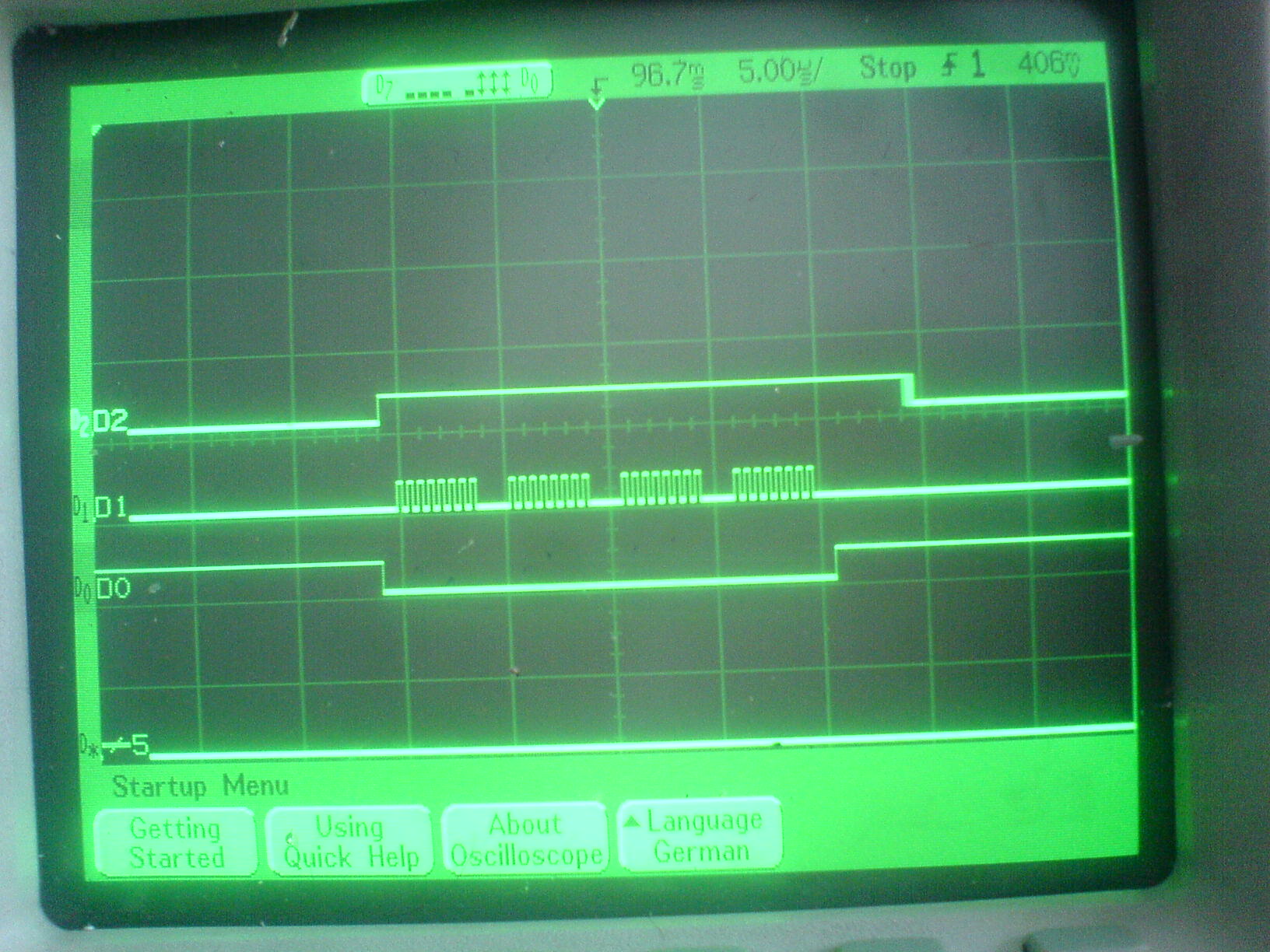
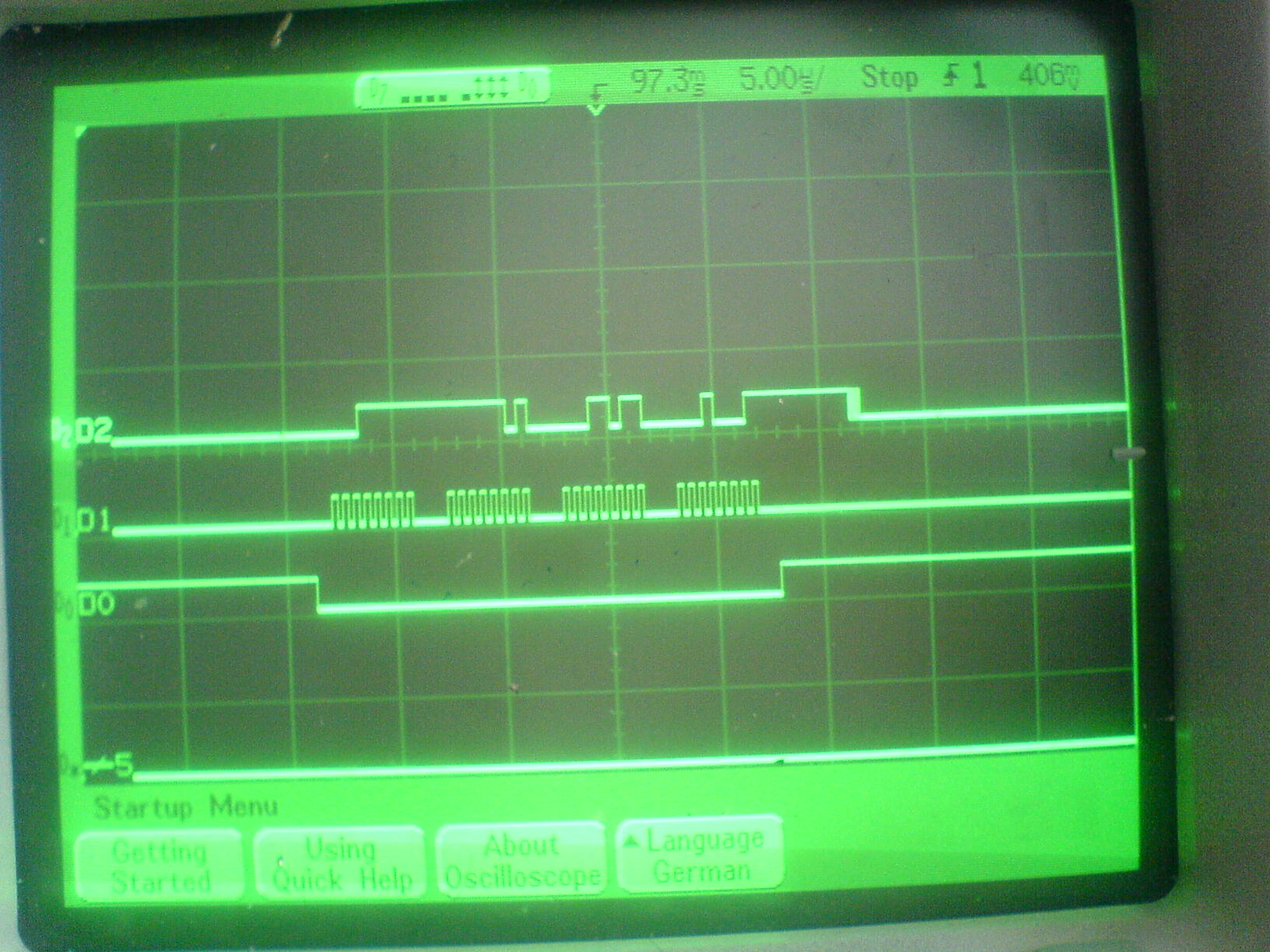
I have a strange problem about LTC2440. Proteus simulation runs perfect, but the SDO pin of ltc2440 gives always logic high at real circuit. I watch the waveform on the scope and see same as this (Note: I draw short form of the wave 4 clock pulses instead of 8 bit).

SDO ___-------------------------------------------------____

SCK _____-_-_-_-___-_-_-_-___-_-_-_-___-_-_-_-__________ (actually 8 pulses in each clock group)

CS --________________________________________----------

I think the problem is about physical. I have added the schematic and source code. How can I fix this problem?

ltc2440.jpg


Code C - [expand]
1
2
3
4
5
6
7
8
9
10
11
12
13
14
15
16
17
18
19
20
21
22
23
24
25
26
27
28
29
30
31
32
33
34
35
36
37
38
39
40
41
42
43
44
45
46
47
48
49
50
51
52
53
54
55
56
57
58
59
60
61
62
63
64
65
66
67
68
69
70
71
72
73
74
75
76
77
78
79
80
81
82
83
84
85
86
87
88
89
90
91
92
93
94
95
96
97
98
99
100
101
102
103
104
105
106
107
108
109
110
111
112
113
114
115
116
117
118
119
120
121
122
123
124
125
126
127
128
129
130
131
132
133
134
135
136
137
138
139
140
141
142
143
144
145
146
147
148
149
150
151
152
153
154
155
156
157
158
159
160
161
162
163
164
165
166
167
168
169
170
171
172
173
174
175
176
177
178
179
180
181
182
183
184
185
186
187
188
189
190
191
192
193
194
195
196
197
198
199
200
201
202
203
#include <18F2520.h>
#device *=16
#fuses INTRC_IO,NOWDT,NOMCLR,PUT,PROTECT,CPB,NOBROWNOUT
 
#use delay(clock=32000000,restart_wdt)
#use rs232(baud=9600,parity=N,xmit=PIN_C6,rcv=PIN_C7,bits=8)
 
//#fuses INTRC_IO,NOMCLR,WDT,WDT64,NOBROWNOUT,PUT,NOLVP,CPB,CPD,PROTECT,NOWRT
 
// Port ve Pin Tanımlamaları ===================================================
#define     ADC_CS_     PIN_C2          
#define     BUSY        PIN_C1
 
#byte   PORTA           = 0xF80
#byte   PORTB           = 0xF81
#byte   PORTC           = 0xF82
#byte   TRISA           = 0xF92
#byte   TRISB           = 0xF93
#byte   TRISC           = 0xF94
 
#byte   SSPSTAT         = 0xFC7
#byte   SSPCON1         = 0xFC6
 
#bit    CKE             = SSPSTAT.6 
#bit    CKP             = SSPCON1.4 
 
#bit    LTC_BUSY        = PORTC.1
#bit    LTC_CS          = PORTC.2
#bit    LTC_SCK         = PORTC.3
#bit    LTC_SDO         = PORTC.4
#bit    LTC_SDI         = PORTC.5
 
#bit    BT_SET_OFFSET   = PORTC.0
#bit    BT_SET_REF      = PORTC.6
 
#bit    OFFSET_SETTING  = PORTA.3
#bit    ILETISIM_LED    = PORTB.3
//==============================================================================
#bit    IA4421_SDI      = PORTA.1
#bit    IA4421_SDO      = PORTA.7 //0
#bit    IA4421_SCK      = PORTA.2
#bit    IA4421_NSEL     = PORTA.5
#bit    IA4421_NFFS     = PORTA.6 //3
#bit    IA4421_NFFS_D   = TRISA.6 //3
#bit    IA4421_NIRQ     = PORTA.4
//===========================================================================
 
int TxPacket[10],RxPacket[10],Paket[80],ALICI_ID_H,ALICI_ID_L,VERICI_ID_H,VERICI_ID_L,LOAD_KG_8L,LOAD_KG_8H;
int16 Frequency_cmd,Transmitter_control_cmd,Data_rate_cmd;
 
//-------------------------------------------------------
#define EPROM_OFFSET_ADDRESS        0x00
#define EPROM_REF_POINT_ADDRESS     0x04
#define EPROM_REF_VALUE_ADDRESS     0x09
//-------------------------------------------------------
 
float data,calc;
int32 offset, ref_adc, ref_kg, load_kg;
 
struct fourbytes 
{ 
    int8 d0; 
    int8 d1; 
    int8 d2; 
    int8 d3; 
}; 
 
union
{
    signed int32 bits32;
    struct fourbytes by;
} load;
 
//-------------------------------------------------------
 
 
#include <math.h>
#include <stdio.h>
 
#define RF_CHANNEL  39
#define ID_HIGH     14
#define ID_LOW      14
 
#include <IA4421_4th_GENERATION.h>
//===========================================================================
 
//===========================================================================
// MAIN Routine 
void main(void)
{
    int16 i,RF_Tolerans;
    //---------------------------------------------------------------------------
    setup_oscillator(OSC_32MHZ);
    restart_wdt();
    
    set_tris_a(0x5B);
    set_tris_b(0x61);
    set_tris_c(0x02); //14


    PORTA=0;
    PORTB=0;
    PORTC=0;
    
    
    output_high(ADC_CS_);
    setup_spi(SPI_MASTER|SPI_L_TO_H|SPI_CLK_DIV_16|SPI_SS_DISABLED);
    CKP = 0; // Set up clock edges - clock idles low, data changes on
    CKE = 1; // falling edges, valid on rising edges.
 
 
    enable_interrupts(global);
    restart_wdt();


    IA4421_init(RF_CHANNEL,7);
    Set_RF_Rx();
    restart_wdt();
    
    delay_ms(100);
    restart_wdt();
    
    
    VERICI_ID_H = ID_HIGH;
    VERICI_ID_L = ID_LOW;
    ALICI_ID_H = VERICI_ID_H;
    ALICI_ID_L = VERICI_ID_L;
    
    IA4421_init(RF_CHANNEL,7);
    Set_RF_Rx();
    
    while(1) 
    {
        i++;
        if(RF_Tolerans<250)
            RF_Tolerans++;
            
        if(RF_Tolerans>249 && !Receive_Packet())
        {
            ILETISIM_LED=(i/1000)%2;
            
            load_kg=0;
            
//          output_low(ADC_CS_);
            
            LTC_CS=0;
 
            load.by.d3 = spi_read(0x78);
            load.by.d2 = spi_read(0x78);
            load.by.d1 = spi_read(0x78);
            load.by.d0 = spi_read(0x78);
            
            LTC_CS=1;
            
//          output_high(ADC_CS_);
            
            // Subtract offset (result is in 2’s complement)
            load.bits32 = load.bits32 - 0x20000000;
            data = (float) load.bits32; // cast as float
            
//          calc=((data-offset)*max_kg)/(max_adc-offset);
            calc=ref_kg*(data-offset)/(ref_adc-offset);
            load_kg=load.bits32;
//          load_kg=calc;
            
            
//          LOAD_KG = 1000;
 
 
            LOAD_KG_8L=make8(LOAD_KG,0);
            LOAD_KG_8H=make8(LOAD_KG,1);
            restart_wdt();
        }
 
        if(Receive_Packet())
        {
            RF_Tolerans=0;
            ILETISIM_LED=!ILETISIM_LED;
            
            if(RxPacket[4]==0x07)
            {
                Set_RF_Tx();
                restart_wdt();
                TxPacket[4] = 0x06;                          // KOMUT
                TxPacket[5] = LOAD_KG_8L;                    // BİLGİ
                TxPacket[6] = LOAD_KG_8H;                    // BİLGİ
                TxPacket[7] = make8(LOAD_KG,2);                 // BİLGİ
                TxPacket[8] = make8(LOAD_KG,3);                 // BİLGİ
                TxPacket[9] = CALCULATE_CRC(TxPacket,9);     // CRC
                Send_Data(10);
                restart_wdt();
                Set_RF_Rx();
                restart_wdt();
            }
 
        }
        
        restart_wdt();
    }//end of while 
}   
//===========================================================================


Maybe because setting Serial Data Input= ''1''? :cool:
This pin is used to select he speed/resolution of the converter. If SDI is grounded (pin compatible with LTC2410) the device outputs data at 880Hz with 21 bits effective resolution. By tying SDI HIGH, the converter enters the ultralow noise mode (200nVRMS) with simultaneous 50/60Hz rejection at 6.9Hz output rate.

http://cds.linear.com/docs/Datasheet/2440fd.pdf
 

No change. But sometimes it give different values rondomly. I wonder if the problem is caused by PIC frequency. May it possible?
I had connected SDI pin to PIC and same problem was happened.
 

I tied SDI pin to GND and i read the values every 20 loop period. However data is like rondom. What can i do more?
 

The converter is in external SCK mode, what’s the frequency of the clock signal driving SCK during the data output?
 

The frequency of SCK is 2 MHz.

The problem is shown in the picture. All things are on same position. But adc sends data like randomly.


Each groups are zoomed:


Attachments

  • DSC01139.JPG
    DSC01139.JPG
    288.8 KB · Views: 66
Last edited:

For the LT2440:
the speed change from 6.9Hz to 880Hz is implemented by simply driving the SDI pin from low to high. Alternatively, the speed can be increased in nine steps (5-bit input to SDI) from 6.9Hz to 3.5kHz
.
Maximum up to 3.5kHz Output Rate so just try to display the raw value received from the ADC as a 32-bit hex value every 500 ms.
SDI pin = low, > SCK = 6.9Hz
SDI pin = high > SCK = 880Hz

https://cds.linear.com/docs/Application Note/an96fa.pdf
https://cds.linear.com/docs/LT Journal/LTC2440_Mar03.pdf

If you are using external SCK (generated by the microcontroller) the EXT pin is tied low for this mode, so in this case BUSY signal is not used for your design.
 

Hi again. I have changed the circuit and the software in accordance with the product datasheet. EOC is checked every 32 bit spi reading if conversion is active. The BUSY interrupt gets logic high after the last SCK clock. (External SCK and single conversion, 3 wire SPI)

All pictures show the same reading action (both Vin- and Vin+ pins are connected to GND). SDO output waveform are still different. And EOC=0 in all reading action as well.

I'm still in trouble :(

Preferences like this:

OSC Frequency = 32 MHz
Timer 2 = 508.13 Hz setup_timer_2(T2_DIV_BY_16,82,12); // timer is 508.13 Hz
SCK is generated by timer2 setup_spi(SPI_MASTER|SPI_L_TO_H|SPI_CLK_T2|SPI_SS_DISABLED);

DSC01206.JPG

DSC01207.JPG

DSC01208.JPG
 

And for the new circuit SDI pin level high? (SCK = 880Hz)
 

SDI is connected to GND, so conversion rate is 880 hz. Do I have to set the timer2 for 880 hz or above (for ex. 886 hz)?
 
Last edited:

If SDI=GND conversion rate =6.9Hz. Need to connect SDI to ''High''.
 

No change. Still I receive unstable data.
 

Status
Not open for further replies.

Similar threads

Part and Inventory Search

Welcome to EDABoard.com

Sponsor

Back
Top