zipfactor
Newbie level 5
Hey everyone,
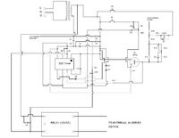
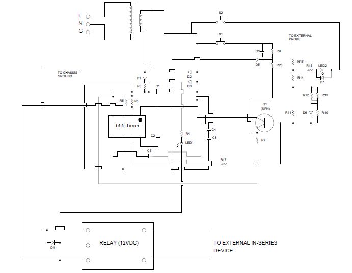
I am trying to troubleshoot a board that had been damaged by water recently. The function of this board is to check for a signal from a probe, and if that signal is not present, to turn off the relay which controls an in-series device. I have checked the transformer output, the diodes, transistor, and checked for any open resistors and have come up with no bad components. Something that I noticed is the 555 timer chip has 14.4VAC on all of its pins. I checked the output of the transformer itself and it is outputting 14.4VAC. It seems to me that the rectifying diodes are not working (would assume DC output to the 555 timer), although when I test them they are good.
In looking at the circuit, I also noticed that the secondary of the transformer goes to straight to the ground pin of the 555 timer. Any ideas on why the circuit designer may have done this?
Any help on where to look next would be appreciated. Attached is a diagram of this circuit.
-zip