Continue to Site

Welcome to EDAboard.com

Welcome to our site! EDAboard.com is an international Electronics Discussion Forum focused on EDA software, circuits, schematics, books, theory, papers, asic, pld, 8051, DSP, Network, RF, Analog Design, PCB, Service Manuals... and a whole lot more! To participate you need to register. Registration is free. Click here to register now.

Low voltage, high current supply - 1.3V/60A

Status
Not open for further replies.
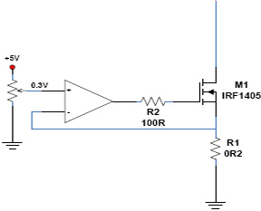
no, but possible do experiments with feedback and overcurrent sections of pwm controller
As far as i know, the lazer diodes use built-in photosensors for restriction of power and only current regulations may be is not enough.
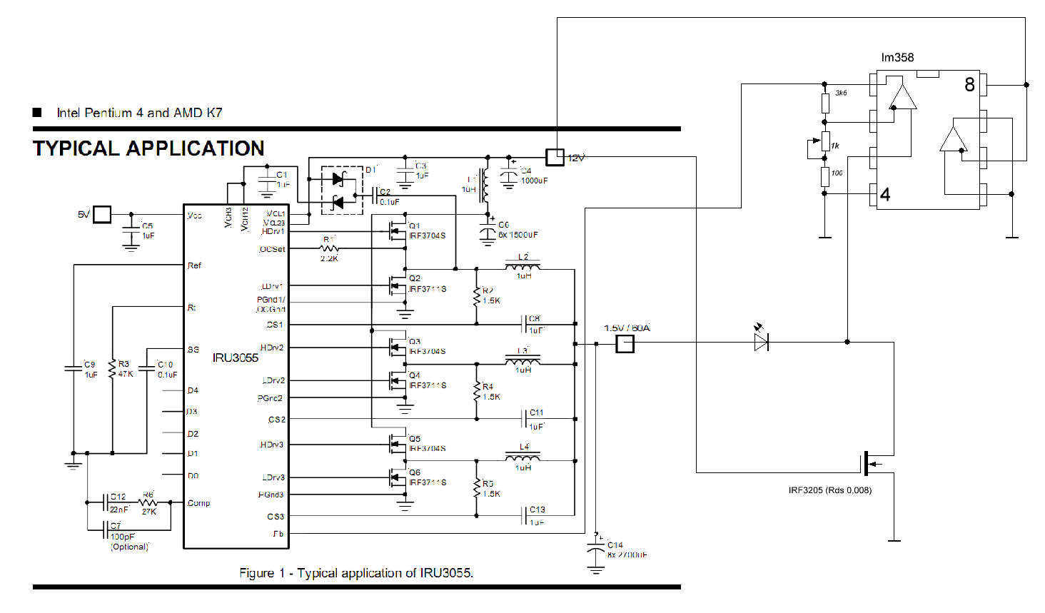
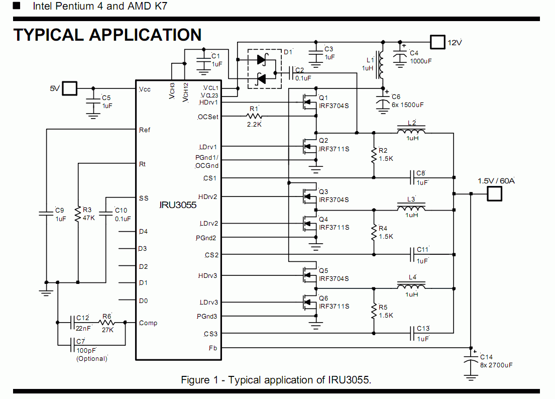
Or can be there is sense to do current regulation on MCU base which can expose respective code on IRU (or similar PWM) input pins.
 
Last edited:

My soldering gun contains a step-down transformer. It takes 120VAC and creates 0.1 VAC at sufficient amperes to heat a thick copper wire red hot.

The secondary is just one or two windings of 8 gauge wire.

If you were to add a few more windings it might be an easy way to get a 1.3V, 60A supply.
 

May be is better use PC PSU without any changes with PWM system from motherboard, such as based on IRU3055
Hi all,
I think that We have some methods to make power supply:
- Use 400W ATX PSU: take 3v3 wire coil after reroll back to 1V5 (there any DIODE powers 100A/20V) such as iop95. Do not change controller part because of PSU controlled by voltage is 5V and 12V. You connect 5V supply with load resistor is 0.22Ohm.
- Such as Deepone, You only need setting any D4,D3,D2,D1,D0 bit is 10110 by D4 bit connect to 5V, D3 connect to GND, D2 connect to 5V...etc. The methods is the simplest.

- - - Updated - - -

May be is better use PC PSU without any changes with PWM system from motherboard, such as based on IRU3055
Hi all,
I think that We have some methods to make power supply:
- Use 400W ATX PSU: take 3v3 wire coil after reroll back to 1V5 (there any DIODE powers 100A/20V) such as iop95. Do not change controller part because of PSU controlled by voltage is 5V and 12V. You connect 5V supply with load resistor is 0.22Ohm.
- Such as Deepone, You only need setting any D4,D3,D2,D1,D0 bit is 10110 by D4 bit connect to 5V, D3 connect to GND, D2 connect to 5V...etc. The methods is the simplest.
 

You may control current by controlling voltage (somewhat easy for liniar loads) but for fast BW it's much better to put an output current sensing device and setup a current loop controller. ATX psu (TL494 as any other PWM controller) allow to control pulse width, respectively output voltage by comparing a feedback (part of output) with a reference. Circuit presented by DeepOne may be a better solution and may uise a lower unregulated voltage (5-7V) to reduce power dissipation. 12V it's used in PC because high BW requested by CPUs (to avoid reset at CPU states high power rate demanding) and it's an ATX standard exisiting voltage bus.
 

I dont think that PC CPU uses 12V, its for Hard Disks and other 12V devices. In some cases you can have lots of this devices such as in one server for example.

;-)
 

PC CPU use 1.2 - 1.8V / 60-120A by a multi-phase converter from 12V bus voltage. This converter is near CPU socket on mainboard and use high frequency (0.2-1MHz). Similar converter (small power) is used to supply voltage for memory. Both converters communiocate with BIOS to setup output voltage accordingly CPU and memory installed; same maniboards allow to modify these voltage w/o restart (very appreciated by overclockers... :) ).
 

...
I need 1.3 V.

i think the focus should be on how to manage and control the current, and not this voltage. i might be wrong, but this laser diode must behave similar to any other LED diode which has a specified nominal forward voltage drop ( 1.3v in your case), and a rated max current ( 60A ).

so like any other diode, we have to ensure that the current stays below 60A. The voltage will manage itself.

however the main challenge is to create such a current source which is realistic. For example even a 0.033 ohm resistor in series with only a 3.3v source would need to dissipate approx 130watts
( 3.3v - 1.3v) / 0.033 = ~60 amps.

Or a 0.05ohm resistor in series would allow ~40 amps, and dissipate 80 watts. This could be created using 20x 1ohm/ 5watt resistors in parallel. but it is not neat solution, and less than even 50% efficient

best thing is to use current regulation using very low Rds mosfets. but focus must be on current control, and not voltage matching.

also your experiment with LTC3738 and 0.2 ohms which smoked. i assume you set the VID for 1.3v across 0.2 ohm. did you use a 10w resistor ? less than 10w you will see smoke of course.
 

I set 1.3 V. and I plugged 4 10W resistors in parallel (result 0.2 ohm). Smoke was from transistors.

"best thing is to use current regulation using very low Rds mosfets"

Any example ?
 

I set 1.3 V. and I plugged 4 10W resistors in parallel (result 0.2 ohm). Smoke was from transistors.
Okay now I have to wonder what your layout looked like if you had room to plug in four 10W resistors on each phase... I also have to wonder how you got 10A out of such a circuit in the first place. The LTC3738 has a max current sense threshold of about 75mV, so with Rsense=0.2ohm it should never allow more than 375mA per phase, or about 1A total out. I think there must have been something very wrong with how you set up the controller...

If you want to go the SMPS route, I would recommend finding a controller similar to the LTC3738 (polyphase buck converter), but not one specialized for controlling CPU power supplies or anything. Having such specialized controllers is usually just trouble for people like you who want to use it for a completely different purpose. You'd be better off with a general purpose polyphase controller, like the LTC3829. You will still need to modify its control scheme in order to force it to regulate current, rather than voltage. This will require some external circuitry: use a shunt resistor to sense current through the diode, and connect that to an external error amplifier. The reference to the error amp will also be external, which will allow easy adjustment of the current setpoint. The output of the error amplifier can drive the Ith pin directly, thus implementing a current-mode current regulator.
 

I set 1.3 V. and I plugged 4 10W resistors in parallel (result 0.2 ohm). Smoke was from transistors.

"best thing is to use current regulation using very low Rds mosfets"

Any example ?

well i was thinking as i went along. but here's a basic and standard circuit
1790793600_1357224829.jpg


your laser can be connected between the mosfet source and the sense resistor.
the sense resistor needs to be selected - say 0.01 ohms/ >50watts. Then the preset on opamp input can be set for 0.5v
Vpower on mosfet drain can be 3.3v. Then dissipation on mosfet will be ( 3.3v - 1.3v - 0.5v) x 50A ~ 75watts

actually not better than just having just resistor in series, but at least there is some control on the current with poetntiometer.

switched design of better efficiency i do not know how to do, sorry
 

Okay now I have to wonder what your layout looked like if you had room to plug in four 10W resistors on each phase... I also have to wonder how you got 10A out of such a circuit in the first place. The LTC3738 has a max current sense threshold of about 75mV, so with Rsense=0.2ohm it should never allow more than 375mA per phase, or about 1A total out. I think there must have been something very wrong with how you set up the controller...

If you want to go the SMPS route, I would recommend finding a controller similar to the LTC3738 (polyphase buck converter), but not one specialized for controlling CPU power supplies or anything. Having such specialized controllers is usually just trouble for people like you who want to use it for a completely different purpose. You'd be better off with a general purpose polyphase controller, like the LTC3829. You will still need to modify its control scheme in order to force it to regulate current, rather than voltage. This will require some external circuitry: use a shunt resistor to sense current through the diode, and connect that to an external error amplifier. The reference to the error amp will also be external, which will allow easy adjustment of the current setpoint. The output of the error amplifier can drive the Ith pin directly, thus implementing a current-mode current regulator.


Rsense - what do You mean by Rsense ? If You look on circuit in LTC3738 datasheet (page 30), You can see Sense 1 - 3 and resistors. In this point I have the same like in datasheet - 0.002 ohm.
4 10W resistors in parallel (result 0.2 ohm) - I plugged to output from all circuit.
 

Rsense - what do You mean by Rsense ? If You look on circuit in LTC3738 datasheet (page 30), You can see Sense 1 - 3 and resistors. In this point I have the same like in datasheet - 0.002 ohm.
4 10W resistors in parallel (result 0.2 ohm) - I plugged to output from all circuit.

it is not clear what you did here.
0.002 ohm vs 0.2 ohm ? 4 resistors in parallel to give 0.2 ohm means you used 0.8 ohm resistors ? this is non-standard value. please explain further ??
 

Bez tytułu.jpg


Picture shows what I did. I used 0,124 ohm - sorry for my mistake (4 x 0,5 ohm 10 w in parallel).
 

Ok you were referring to the load resistance, rather than the current sense resistors.

So if you blew a FET, did you try and find out why? Was it an immediate failure on startup, or did some parts gradually exceed there temperature limits? Did the circuit work well at lower currents?

There are many possible reasons for the failure. Poor layout, insufficient device ratings or heatsinking, bad solder joints, etc. Do you have a picture of the circuit under test?
 

So,I was checking current on multimeter. First, I was loading current about 5 A and testing about 2-3 minutes- was ok (but coils were very hot). Next I increase current to about 10 A, after 5-10 seconds I was feeling smoke.
I'm thinking why, datasheet say: up to 65 A, I had 10, so this is 17 %.
 

So,I was checking current on multimeter. First, I was loading current about 5 A and testing about 2-3 minutes- was ok (but coils were very hot). Next I increase current to about 10 A, after 5-10 seconds I was feeling smoke.
I'm thinking why, datasheet say: up to 65 A, I had 10, so this is 17 %.

so you are saying the inductors burned, and not the mosfet ? and these inductors are rated for 65A or is mosfet rated for 65A ? what freq are you using ?

also, are you using all 3 phases or just one phase ?
 

I think that mosfet burned. Inductors were hot. I used 3 phases.
Schemat is in attachment (In schemat are symbols of inductors and mosfets).Printing Drukuj schemat-page-001.jpg
 

oh good the full schematic !! this should keep us busy for a while.... :)
 

Schematic is the same like in datasheet. Only difference is between some elements - I can't find the same like in original, so I found replacement.
 

Status
Not open for further replies.

Similar threads

Part and Inventory Search

Welcome to EDABoard.com

Sponsor

Back
Top