Continue to Site
Follow along with the video below to see how to install our site as a web app on your home screen.
Note: This feature may not be available in some browsers.
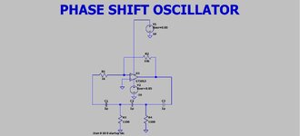
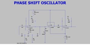
For 1 unit the cost of parts does not matter, but you need Vceo >=500V transistors and you need to specify output impedance Z(f) and load regulation error. This design looks rather high Z.Thanks, its just to give a basic test input to 3 phase equipment.
Circuit shows 47 uF, so I assumed electrolytic or tants....Nothing has be said about using electrolytic caps in the circuit. You surely won't.
RC impedance level could be higher though.

 forum.digikey.com
If you want stability using L:C than focus on the L to get high Q.Thanks Danadakk, ill look into the SOC situation.
At the moment, the analog way looks like only giving one stable sine wave, which needs filtering...hence i am still thinking of the "square wave in to LC tuned to 60Hz".
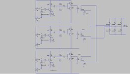
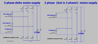
..3 times, and phase shifted 120degs
LTspice and jpeg attached

 electronics.stackexchange.com

 www.allaboutcircuits.com

 www.electrical4u.com
Which circuit? Post #15 shows 4.7 uF, I would expect film capacitor in the first place.Circuit shows 47 uF, so I assumed electrolytic or tants....