Continue to Site

Welcome to EDAboard.com

Welcome to our site! EDAboard.com is an international Electronics Discussion Forum focused on EDA software, circuits, schematics, books, theory, papers, asic, pld, 8051, DSP, Network, RF, Analog Design, PCB, Service Manuals... and a whole lot more! To participate you need to register. Registration is free. Click here to register now.

load pull testing ideas

Status
Not open for further replies.

robismyname

Full Member level 6
Joined
Jan 17, 2008
Messages
390
Helped
11
Reputation
22
Reaction score
9
Trophy points
1,298
Location
Central Florida
Activity points
4,603
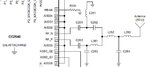
Does anyone know how I can do a load pull test for the attached circuit. Not familiar with this test but I was told that load pulling means varying the complex load impedance until maximum output power is achieved. Couldnt find much by way of google. Nothing in my RF books (wes haywood, joe carr, david rutledge). Nothing relevant on forum as well.

The circuit I am investigating comes from a TI cc2450.

The goal is to figure out how well the BALUN performs by means of load pulling. If anyone can help I need test setup and measurement know how help.

I need help with understanding the test setup and test measurements.
 

Attachments

  • balun circuit.jpg
    balun circuit.jpg
    24.2 KB · Views: 79

Load Pull Technique is used at high power output levels. As I see, all you should do to comjugate match between IC and Balun circuit.
Integrated circuits have generally low output power levels and output impedances are generally defined by manufacturers.Therefore you should find this impedance by checking datasheet or measurement then match this impedance to balun.Balun circuit has real input and output impedances and matcjhing circuit can be implemented between balun and IC.
 

The posted circuit use the LC balun recommended by TI.
Myself I would not use this kind of balun which is pretty narrow band and very sensitive to component variations, especially when use values as 1nH or 1pF, as they use.
 

You can use AnTune do the match. WWW.AnTune.NET

I am not so concerned about doing the match but instead validating the match with a VNA. One side of the vna is differential. How would I connect this to my VNA since my VNA does not support differential inputs?

- - - Updated - - -

Therefore you should find this impedance by checking datasheet or measurement then match this impedance to balun.

Is there a practical way to do measurement of the blaun or the IC considering that it is differential and not single ended?

The IC datasheet says that the differential output is 70+30j. I would like to measure this with a VNA but how do I measure with practicality the impedance of the IC with a VNA when the IC has differential outputs? I would also like to measure the impedance of my balun as well since one side of the balun is also differential.
 

I am not so concerned about doing the match but instead validating the match with a VNA. One side of the vna is differential. How would I connect this to my VNA since my VNA does not support differential inputs?
Connect with the proposed 200 Ohm probe. Set system impedance in AnTune to 200 Ohm. Read correct impedance compensated impedance value in AnTune. Cant be read directly in VNA due to that VNA not know about the probe 1:4 impedance ratio.
As an extra bonus can AnTune also propose a matching network.
An alternative way to find reactive values is to save S11 measurement and afterwards do the calculations in Excel or any else mathematical tool.
As an alternative is it previously proposed to do a VNA two port measurement. A 3:rd alternative is to find a professional differential probe.

The IC datasheet says that the differential output is 70+30j. I would like to measure this with a VNA.
You will measure chip impedance in serial with PCB traces. Not chip alone. Even real short traces will add both inductive and capacitive losses that will affect your design. As TI in proposed network use values around few pF and few nH is it important to include all losses if you intend to use similar values.

It is a bit complicated to measure correct at relative high frequencies. It requires good knowledge about actual VNA and how to practical identify and avoid error sources. An alternative is to copy by TI proposed complete design and just measure final expected 50 Ohm.
Do not omit anything in TI design. By TI proposed LP filter is not just for harmonics, it is also a part of the impedance correcting network at main frequency.
 

“Measuring Differential Impedances with a Two-Port Network Analyzer”,May 01, 2002,MAXIM, APPLICATION NOTE 915
 

Status
Not open for further replies.

Part and Inventory Search

Welcome to EDABoard.com

Sponsor

Back
Top