Continue to Site

Welcome to EDAboard.com

Welcome to our site! EDAboard.com is an international Electronics Discussion Forum focused on EDA software, circuits, schematics, books, theory, papers, asic, pld, 8051, DSP, Network, RF, Analog Design, PCB, Service Manuals... and a whole lot more! To participate you need to register. Registration is free. Click here to register now.

LM7912 regulator output is setting down to zero

Status
Not open for further replies.

kiranhatti

Newbie level 6
Joined
Oct 18, 2013
Messages
13
Helped
0
Reputation
0
Reaction score
0
Trophy points
1
Activity points
110
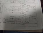
LM7912 regulator output is setting down to zero after the current is drawn by the load. Here I am attaching power supply circuit and DAC circuit. My project is the sensor from the field will give 8 to 48 mA output and which is read by the ADC. After it will be taken to the microcontroller and it will be sent to DAC and the output of the DAC is 4 -20 mA.

Whenever the unit is switched on for some time the output of the DAC is going 45mA which is out of our scaling. There is no linearity between input mAmps and output mAmps. Whenever the output of DAC is 45mA , the output of the 7912 regulator is 0V.

Please let me KNOW is it because of regulator or some other component.?
 
Last edited by a moderator:
Re: LM7912 regulator ouptut is setting down to zero

Hi,

is it a "true" LM7912? or is it an equivalent like TC7912?

7912 is a negative voltage regulator. The input should be at least -15V.

Is the input voltage OK?
Is the device hot?

****

Show us your schematic.

Klaus
 

Re: LM7912 regulator ouptut is setting down to zero

IMG_20150820_172640086.jpg

please find the attached schematic

- - - Updated - - -

The part number is UA79M12C
 

Re: LM7912 regulator ouptut is setting down to zero

The device is getting hot obviously because the input to the ic is -42V.
 

Re: LM7912 regulator ouptut is setting down to zero

Did you check the pin-out ? 78xx and 79xx do not have the same pin-out..
 

Re: LM7912 regulator ouptut is setting down to zero

From your schematic, C22 is rated 16V. Apparently U11 (7824 IC) outputs 24V, which will destroy the capacitor.
 

-48 to -12 @ 48mA is 1.W Watts which needs a good heatsink, otherwise thermal shutdown.

It may work with a series drop resistor between bridge and cap on input to drop Vin to -20V min.

But ADC/DAC other issues must be resolved.
 

C18, C19, C22, C23 are all 16V Capacitors and you are providing 24V and -16V to it.

Change C18 and C22 to 10uF 35V type.

You are using a bridge rectifier circuit. Then why does JP5 and JP6 show three pin interface to transformer. Why Center Tap is used ?
 

Re: LM7912 regulator ouptut is setting down to zero

78xx and 79xx both pinouts are different. You can go through schematics.
 

Re: LM7912 regulator ouptut is setting down to zero

Thank you for your kind reply. I will change to 10UF/25V
 

Thank you for reply.I assumed Center tap is used to get +/-12VDC.
 

Re: LM7912 regulator ouptut is setting down to zero

I changed to 10UF/63V then also 7912 regulator output is getting zero.
 

Did you check the power supply stand-alone (i.e. without any load) ?
 

I can see that the requester used the schematic without reading device specifications.
78XX and 79XX have different pinouts, and the INPUT voltage including spikes must not exceed 35 V,
otherwise the internal reference burns down. Rating capacitors for safe voltages is the very basic rule.

Please do not continue without learning the specifications. Learn the basics, or you will burn more components.
 

Thank you for your reply. You are right the input voltage including spikes must not exceed 30V. Since it is proved project i did not check the specifications. The input voltage from the transformer is 28VAC and it is rectified and the voltage to the regulator becomes almost 42VDC. So may be i have to reduce the transformer output voltage to 18VAC. I think it will become alright.
 

Hi,

maybe the overvoltage caused a "little" damage on the 7912. Maybe replace it with a new one.

But reducing input voltage is recommended.

Klaus
 

I have reduced the input voltage to -28VDC. It is working fine now. But i have to test it for long time.

Thank you for your kind help.
 

Till now there is no problem. I think it works .

Thank you for your support.
 

Status
Not open for further replies.

Similar threads

Part and Inventory Search

Welcome to EDABoard.com

Sponsor

Back
Top