baby_1
Advanced Member level 1

- Joined
- Dec 3, 2010
- Messages
- 415
- Helped
- 1
- Reputation
- 2
- Reaction score
- 1
- Trophy points
- 1,298
- Activity points
- 4,277
Hello
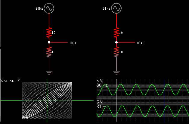
we wanted to find the angle difference of two analog input signal in my university lab.as three group tested and show the result our information that we got from oscilloscope was acceptable.but we have a important question that one of the other group asked us.
here is my step to test our circuit.
1-we inject a 10khz frequency with 1VP.P amplitude to input circuit and channel 1 oscilloscope and set volt division on 1 volt
2-we find the wave form frequency amplitude with channel 2 and with volt division 5mv (the output amplitude was less than 10mv)
3-we find the angle difference in X-Y mode and with lisagor curve
4-we increase the wave frequency to 1Mhz (with step 100Khz) and write the output voltage and angle difference between channel one and two
as i said before our result was acceptable but some one asked me a strange question.if we change the volt division we got the different result( doesn't it?)
if we want to see lissajous curve is it important to set the channel 1 and 2 volt division to same value (for examlple 1Vpp)?
if yes why our result was acceptable?
Thanks
Last edited: