PRIYADHARSHINI PALANISAMY
Member level 2
Hi all,
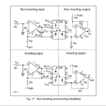
I am using IL300 Linear opto coupler to isolate the analogue signals..Here I have attached the picture for four configurations of IL300..I m configuring my circuit as Non Inv input to Non Inv output...
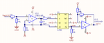
I have Designed my circuit for + and - 5 V as my supply.I attached my schematic design for your referance.And i got output at OUT1 as follows:
for 0V input I got 2.4V at the 5 th pin(OUT1)
for 5V input I got 4.43V
In between this ranges the output will be linear.
Now I want to consider the offset that is 2.4V should be reduces to 0v
I need 0V for 0V input
4.5V for 5V input.
For this purpose the second stage of the opamp has been built.I don t know how to select the resistor values.they have given the formula.according to that i have selected my resistor values as 30K and 40K .but i got the output(OUT2) 4.01 V for 2.4V and 4.43V input.I don t know how to choose the values to clear the offset
Thanks in Advance
I am using IL300 Linear opto coupler to isolate the analogue signals..Here I have attached the picture for four configurations of IL300..I m configuring my circuit as Non Inv input to Non Inv output...
I have Designed my circuit for + and - 5 V as my supply.I attached my schematic design for your referance.And i got output at OUT1 as follows:
for 0V input I got 2.4V at the 5 th pin(OUT1)
for 5V input I got 4.43V
In between this ranges the output will be linear.
Now I want to consider the offset that is 2.4V should be reduces to 0v
I need 0V for 0V input
4.5V for 5V input.
For this purpose the second stage of the opamp has been built.I don t know how to select the resistor values.they have given the formula.according to that i have selected my resistor values as 30K and 40K .but i got the output(OUT2) 4.01 V for 2.4V and 4.43V input.I don t know how to choose the values to clear the offset
Thanks in Advance