Continue to Site

Welcome to EDAboard.com

Welcome to our site! EDAboard.com is an international Electronics Discussion Forum focused on EDA software, circuits, schematics, books, theory, papers, asic, pld, 8051, DSP, Network, RF, Analog Design, PCB, Service Manuals... and a whole lot more! To participate you need to register. Registration is free. Click here to register now.

Learning circuit analysis

Status
Not open for further replies.

LearningElectronics10

Newbie level 4
Joined
Nov 29, 2015
Messages
5
Helped
0
Reputation
0
Reaction score
0
Trophy points
1
Activity points
56
I would like to learn how to analyise circuits involving capacitors, coils, LC tanks etc


For example I already know the theory of how an astable multivibrator operates, but I would like to be able to analyse the circuit precisely from start to finish using mathematics.
tim20.gif


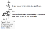
I would like to also be able to answer questions such as what role does the capacitor play connected between the base and ground in the simple below circuit. If the capacitor was connected to the positive terminal in parallel to the resistor it is pretty straightforward to me: it enforeces/helps the feedback from the LC tank to the emitter.

article-2012march-designing-tx-only-rf-fig2.jpg


Another question would be: What is the role of Eulers number when calculating RC circuits - I was unable to find an explanation on the internet of the purpose of the e number in the formula.


Where do I get started, what are the best websites, books for me?

I would also like to learn some of the mathematics for electronics and I would like to know if there is a book teaching math concepts such as calculus alongside electronic problems, as I feel this is the easiest way to learn.

Essentially I would like to be able to do what LTSpice can do but using a pencil and paper - this is what I would call "understanding electronics"

Ofcourse help on the mentioned problems/circuits will be also very appreciated.
 

Another question would be: What is the role of Eulers number when calculating RC circuits - I was unable to find an explanation on the internet of the purpose of the e number in the formula.

It is basically the response to a step input of a circuit which have reactive components forming first order equations. This number is obtained through a mathematical transformation (Laplace) of domains, from time to frequency, and back to time. The reason behind doing that conversion is due to the easiness to make some operations with the variables transformed.
 

The transistor VHF oscillator uses the transistor as a common base amplifier so the capacitor to ground at the base grounds the base at high frequencies but still allows audio at its much lower frequencies to modulate the base voltage producing frequency modulation (FM) and a little AM.

A good book is The Art Of Electronics that was written by a professor at Harvard university. It has 1125 pages. It might still be free on the internet.
 
Another question would be: What is the role of Eulers number when calculating RC circuits - I was unable to find an explanation on the internet of the purpose of the e number in the formula.

We have the standard formula, a capacitor loses 63% of its charge during 1 time constant (RC). It contains the reciprocal of e :

V = (1/ e )^x
 
To explain formula in my earlier post:

V = ( 1/ e ) ^x

X is number of time constants.

V is final voltage if starting V was 1V.

Thank you for the explanation. I will have to dive deeper into calculus.

At the moment I understand differentiation in terms of Velocity differentiated equals Acceleration which makes a lot of sens to me. I just need to learn a bit more of it and see how it fits with the capacitor. So far I get that i = C dv/dt - which means that the current decreases with the capacitor charge/voltage, which is a very stratforward and easy observable property of the capacitor. I just need to be able to figure out how to apply/calculate using the formula to find for example how long it takes to charge a capacitor (without using time constants which are derived from the equation). I have noticed that the Euler's number is actually a mathematical number aiding in solving the equation. Thats all I know about solving capacitor circuits at the moment.
 

Because a common base amplifier transistor like this one should have its base grounded (common) at the oscillator frequency.

But I don't understand how that is related and if it is part of the feedback network, I have never seen the base grounded in a NPN setup like this.

If the base was hooked up via a capacitor to the positive terminal that would make a lot of sense to me, as when current in the emitter increases (supplied via the feedback capacitor from the LC tank) it flows through the emitter via the base and the capacitor connected to the positive terminal.
 

I told you the transistor is a Common Base Amplifier but you did not know anything about it and you did not look it up. The emitter is the input and the collector is the output. The capacitor from collector to emitter provides positive feedback so it can oscillate.
 

Attachments

  • common base transistor.png
    common base transistor.png
    10.9 KB · Views: 60

Status
Not open for further replies.

Similar threads

Part and Inventory Search

Welcome to EDABoard.com

Sponsor

Back
Top