jayanth.devarayanadurga
Banned
- Joined
- Dec 4, 2012
- Messages
- 4,280
- Helped
- 822
- Reputation
- 1,654
- Reaction score
- 791
- Trophy points
- 1,393
- Location
- Bangalore, India
- Activity points
- 0
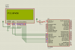
@wp100. Please look my new code which is attached with Proteus file. You only have to look in the PutSting function. In that I have three different ways for printing strings. They are
2 functions and 1 macro
1 call send_nibbles
2 call LCD_DATA
3 macro LCD_D
Only one of them is used. The problem is in K8LH code I attached the w (Working register) is going to lcd_d function but in my code it is not working and that is causing the problem. See my attached simulation by compiling by selecting any one function call or macro in the PutString function and assembling the code. My LCD_Chr macro works fine but same when a similar macro which is LCD_D is called from PutString w is not going into the macro. My way of LCD is different because it allows to use any pins for LCD control and data. You don't have to use D4-D7 of some PORT but can use any random digital output pins for lcd data and control. My LCD_Chr works fine there is no Problem. Problem is in PutSting function which is called from LCD_Out macro which is used to print strings.
I will explain it little more clearly
In PutString function
movf TABLAT,w puts the current character of the string in w (working register) and then LCD_D macro is called in my version but in K8LH version lcd_d function is called. In K8LH version w is going into lcd_d function and saved temporarily in a file register and then restored back to w (reg) and then assigned to LCD_PORT (D4-D7). In my version w from PutString is not going to LCD_D macro. In LCD_D macro
movwf LCDChr
is used and then
if LCDChr & H'10'... is used to
So, it has to work like this
from movf TABLAT,w the current character of the string will be in w and w has to go to LCDChr and LCDChar compared with hex values will toggle the data pins of LCD like it is doing in my LCD_Chr macro which is printing single characters.
@betwixt. I am waiting for your code.
If I use
#define LCD_PORT LATB
...
banksel LCD_PORT
...
it is working i.e., I have to use D4-D7 of some port but not working for bit i.e., How to select bank which has the following bits. This is actuallly causing the problem.
#define LCD_D4 LATB,4
#define LCD_D5 LATB,5
#define LCD_D6 LATB,6
#define LCD_D7 LATB,7
Edit 2:
I found the problem. I debugged the code in mplab and also mplabX. What I observed is
When I step-into LCD_Out macro call program execution goes directly to Delay500us instead of going to LCD_Out macro or PutString function which is called in the LCD_Out macro. If I comment the Delay500us function and function calls in the code and debug then it executes normally entering the PutString function call. Another thing I observed is in the PutString function send_nibbles function is called. In this none of the if...else...endif function work i.e., it always executes the else conditions. So I used MACROS.ASM with my code and used select...endselect method in the send_nibbles function. Now the execution happened as expected without problem but LCD doesn't display because Delay500us is needed for LCD_STROBE. If I uncomment the Delay500us and debug or run the code the execution just goes into Delay500us call and comes out of it and repeats and it doesn't execute any other code. What might be the problem?
I am attaching the file I used for debugging. I have commented out the Delay500us function and its calls. Without that function it doesn't display but by debugging it can be made sure that it executes as needed. If Delay500us is uncommented then no other code executes.
Attachments
Last edited:

 4.
4.