Continue to Site

Welcome to EDAboard.com

Welcome to our site! EDAboard.com is an international Electronics Discussion Forum focused on EDA software, circuits, schematics, books, theory, papers, asic, pld, 8051, DSP, Network, RF, Analog Design, PCB, Service Manuals... and a whole lot more! To participate you need to register. Registration is free. Click here to register now.

[SOLVED] DSPIC30f2010 4 wire LCD interfacing mplab

Status
Not open for further replies.

Rizwan96101

Newbie
Joined
Sep 10, 2023
Messages
4
Helped
0
Reputation
0
Reaction score
0
Trophy points
1
Activity points
64
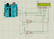
I have to interface 16 by 2 lcd with DSPIC30f2010 microcontroller via CD4015 shift register using only 4 wires (RS,EN,Data, CLK). I have done it in proteus using arduino but the same logic is not working on DSPIC30f2010.
 

Attachments

  • WhatsApp Image 2023-09-10 at 1.40.23 PM.jpeg
    WhatsApp Image 2023-09-10 at 1.40.23 PM.jpeg
    192.5 KB · Views: 82
  • WhatsApp Image 2023-09-10 at 2.06.10 PM.jpeg
    WhatsApp Image 2023-09-10 at 2.06.10 PM.jpeg
    168.9 KB · Views: 82

This is a very badly worded question. Also I don't see how the photo relates to the schematic.
You say the code works with the Arduino - you will need to show us that code so we know what you are aiming at.
You say that it doesn't work with a dsPIC30F2010 but you don't say in what way it is not working. What is it supposed to do? Show us the code you are using (there a numerous things that can stop these very old processors from working if you don't set them up correctly.
Susan
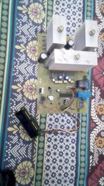
I am very sorry that I have posted for the first time here and after sending my message i lost this thread.I was finding it to add details. I just caught it through my email. The Arduino code on the LCD attached with the lcd of the inverter board (purchased from Market) is working fine on the LCD as well as the in the proteus simulation (right picture). The code written for the arduino is given below,

Code C - [expand]
1
2
3
4
5
6
7
8
9
10
11
12
13
14
15
16
17
18
19
20
21
22
23
24
25
26
27
28
29
30
31
32
33
34
35
36
37
38
39
40
41
42
43
44
45
46
47
48
49
50
51
52
53
54
55
56
57
58
59
60
61
62
63
64
65
66
67
68
69
70
71
72
73
74
75
76
77
78
79
80
81
82
83
84
85
86
87
88
89
90
91
92
93
94
95
96
97
98
99
100
101
102
103
104
105
106
107
108
109
110
111
112
113
114
115
116
117
118
119
120
121
122
123
124
125
126
127
128
129
130
131
132
133
134
135
136
137
138
139
140
141
142
143
144
145
146
147
148
149
150
151
152
153
154
155
156
157
158
159
160
161
162
163
164
165
166
167
168
169
170
171
172
173
174
175
176
177
178
179
180
181
182
183
184
185
186
187
188
189
190
191
192
193
194
195
196
197
198
199
#define LCD_RS 8
#define LCD_E 9
#define Data_Pin 4
#define Clk_Pin 5
//#define D6 6
//#define D7 7
void lcdwrite(int select, char data)
{
  digitalWrite(Clk_Pin,LOW);
  digitalWrite(LCD_RS, select);         //Change RS for command/data
  char LcdDataBus = (data >>4 );     //Send higher nibble
 
  char Maask = 8, Flaag=0;
  for (int t=0; t<7; t++)
  {
   Flaag = LcdDataBus & Maask;
   if(Flaag==0)
   digitalWrite(Data_Pin, LOW);
   else
   digitalWrite(Data_Pin, HIGH);
   digitalWrite(Clk_Pin, HIGH);
   delayMicroseconds(100);
   digitalWrite(Clk_Pin,LOW);
   Maask = Maask >> 1; 
  }
  digitalWrite(LCD_E, HIGH);
  delay(2);
  digitalWrite(LCD_E, LOW);
  delay(2);
   LcdDataBus = (data & 0x0f );  //Lower nibble
   Maask = 8, Flaag=0;
  for (int t=0; t<7; t++)
  {
   Flaag = LcdDataBus & Maask;
   if(Flaag==0)
   digitalWrite(Data_Pin, LOW);
   else
   digitalWrite(Data_Pin, HIGH);
   digitalWrite(Clk_Pin, HIGH);
   delayMicroseconds(100);
   digitalWrite(Clk_Pin,LOW);
   Maask = Maask >> 1; 
  } 
 digitalWrite(LCD_E, HIGH);
  delay(2);
  digitalWrite(LCD_E, LOW);
  delay(2);   
}
void lcd_cmd(char cmd)
{
  lcdwrite(0, cmd);
}
void lcd_data(char dat)
{
  lcdwrite(1, dat);
}
void lcd_ini()
{
  //Lcd_CmdWrite(0x02);        // Initialize Lcd in 4-bit mode
   // Lcd_CmdWrite(0x28);        // enable 5x7 mode for chars
    //Lcd_CmdWrite(0x0E);        // Display OFF, Cursor ON
    //Lcd_CmdWrite(0x01);        // Clear Display
    //Lcd_CmdWrite(0x80);
  lcdwrite(0, 0x02);//lcdwrite(0, 0x33);
  delay(15);
  lcdwrite(0, 0x28);//lcdwrite(0, 0x32);
  delay(15);
  lcdwrite(0, 0x0E);//lcdwrite(0, 0x28);
  delay(15);
  lcdwrite(0, 0x01);
  delay(15);
  //lcdwrite(0, 0x0C);
  //delay(15);
  //lcdwrite(0, 0x06);
  delay(15);
  lcdwrite(0, 0x80);
  delay(15);
}
 
 
void setup() {
  // put your setup code here, to run once:
 
  pinMode(4,OUTPUT);
  pinMode(5,OUTPUT);
  pinMode(6,OUTPUT);
  pinMode(7,OUTPUT);
  pinMode(8,OUTPUT);
  pinMode(9,OUTPUT);
 
  delay(150);
  lcd_ini();
  lcd_data('h');
  lcd_data('e');
  lcd_data('y');
 //lcd_data(0x61);
  //lcdwrite(1, 0x08);
}
void loop() {
  // put your main code here, to run repeatedly:
}
 
 
The same logic functions for the DSPIC are given below,
 
void Lcd_CmdWrite(char cmd)
{
   LCD_RS = 0;   // Send LOW pulse on RS pin for selecting Command register
   char LcdDataBus = (cmd >>4);     //Send higher nibble
   char Maask = 8, Flaag=0;
  for (int t=0; t<7; t++)
  {
   Flaag = LcdDataBus & Maask;
   if(Flaag==0)
       Data_Pin = 0;
   else
       Data_Pin = 1;
   Clk_Pin = 1;
   __delay32(5500);
   Clk_Pin = 0;
   Maask = Maask >> 1;  
  } 
  
    //LCD_RW = 0;   // Send LOW pulse on RW pin for Write operation
    LCD_E = 1;   // Generate a High-to-low pulse on EN pin
   delay_ms(5);
    LCD_E = 0;
   delay_ms(5);
 
    LcdDataBus = (cmd & 0x0f); //Send Lower nibble
    LCD_RS = 0;   // Send LOW pulse on RS pin for selecting Command register
    //LCD_RW = 0;   // Send LOW pulse on RW pin for Write operation
    Maask = 8;
    Flaag=0;
  for (int t=0; t<7; t++)
  {
   Flaag = LcdDataBus & Maask;
   if(Flaag==0)
       Data_Pin = 0;
   else
       Data_Pin = 1;
   Clk_Pin = 1;
    __delay32(5500);
   Clk_Pin = 0;
   Maask = Maask >> 1;  
  } 
    LCD_E = 1;   // Generate a High-to-low pulse on EN pin
  delay_ms(5);
    LCD_E = 0;
delay_ms(5);
   
}
 
 
void Lcd_DataWrite(char dat)
{
    char LcdDataBus = (dat  >> 4);      //Send higher nibble
    LCD_RS = 1;   // Send HIGH pulse on RS pin for selecting data register
    //LCD_RW = 0;   // Send LOW pulse on RW pin for Write operation
   char Maask = 8, Flaag=0;
  for (int t=0; t<7; t++)
  {
   Flaag = LcdDataBus & Maask;
   if(Flaag==0) Data_Pin = 0;
   else Data_Pin = 1;
   Clk_Pin = 1;
   __delay32(5500);
   Clk_Pin = 0;
   Maask = Maask >> 1;  
  } 
   
    LCD_E = 1;   // Generate a High-to-low pulse on EN pin
   delay_ms(5);
    LCD_E = 0;
 
    delay_ms(5);
 
    LcdDataBus = (dat & 0x0f);  //Send Lower nibble
    LCD_RS = 1;    // Send HIGH pulse on RS pin for selecting data register
    //LCD_RW = 0;    // Send LOW pulse on RW pin for Write operation
   
    Maask = 8;
    Flaag=0;
  for (int t=0; t<7; t++)
  {
   Flaag = LcdDataBus & Maask;
   if(Flaag==0) Data_Pin = 0;
   else Data_Pin = 1;
   Clk_Pin = 1;
   __delay32(5500);
   Clk_Pin = 0;
   Maask = Maask >> 1;  
  } 
    LCD_E = 1;    // Generate a High-to-low pulse on EN pin
   delay_ms(5);
    LCD_E = 0;
 
   delay_ms(5);
}

 
Last edited by a moderator:

In main of DSPIC i have just this code below,

Code C - [expand]
1
2
3
4
5
6
7
8
9
10
11
12
13
14
15
16
17
18
19
20
21
22
23
24
25
26
27
28
29
30
31
32
33
34
35
36
#define Blink1   LATDbits.LATD0
#define Blink2   LATDbits.LATD1
#define LCD_E     LATFbits.LATF2
#define LCD_RS    LATFbits.LATF3
#define Data_Pin  LATEbits.LATE4
#define Clk_Pin  LATEbits.LATE5
main()
{
 Lcd_CmdWrite(0x02);        // Initialize Lcd in 4-bit mode
    delay_ms(5);
    Lcd_CmdWrite(0x28);        // enable 5x7 mode for chars
    delay_ms(5);
    Lcd_CmdWrite(0x0E);        // Display OFF, Cursor ON
    delay_ms(5);
    Lcd_CmdWrite(0x01);        // Clear Display
    delay_ms(5);
    Lcd_CmdWrite(0x80);        // Move the cursor to beginning of first line
delay_ms(5);
 
    Lcd_DataWrite('H');
    Lcd_DataWrite('e');
    Lcd_DataWrite('l');
    Lcd_DataWrite('l');
    Lcd_DataWrite('o');
    Lcd_DataWrite(' ');
   
while(1)
{
    Blink1 =0;
    Blink2 =1;
    delay_ms(1000);
    Blink1 =1;
    Blink2 =0;
    delay_ms(1000);
}
}

 
Last edited by a moderator:

I assume you are using XC16.
Have you defined the _XTAL_FREQ pre-processor symbol that is used in the 'delay_xx" macros? If not then you are almost certainly not getting the delays you intend.
Where do you initialise the LCD (in the dsPIC30F code)?
Also you normally need to set up the oscillator etc but I assume that you have done that with the CONFIG settings that you don't show. (You have this in your Arduino code but you must also initialise the LCD in the dsPIC30F code)
Susan
 

Hi,
Clk_Pin = 1;
__delay32(5500);
Clk_Pin = 0; Maask = Maask >> 1;
this defines the delay after the rising edge. But I miss the delay at the falling edge.

If not defined properly it may cause different results on different (speed) microcontrollers.

Klaus
 

Thanks dear. The problem resolved. The problem was that the LCD two pins being used were of PWM channel 3 and the value set in the wpm control register was wrong due to which these pins were not behaving as normal IO pins. Now i will test the complete code with display on the inverter board. Will ask question here if face some difficulty.
 

Status
Not open for further replies.

Similar threads

Part and Inventory Search

Welcome to EDABoard.com

Sponsor

Back
Top