Continue to Site

Welcome to EDAboard.com

Welcome to our site! EDAboard.com is an international Electronics Discussion Forum focused on EDA software, circuits, schematics, books, theory, papers, asic, pld, 8051, DSP, Network, RF, Analog Design, PCB, Service Manuals... and a whole lot more! To participate you need to register. Registration is free. Click here to register now.

LAyout for microstip line based microwave amplifier circuit.

Status
Not open for further replies.

mhussainshah

Junior Member level 1
Joined
Jan 23, 2010
Messages
17
Helped
0
Reputation
0
Reaction score
0
Trophy points
1,281
Location
Glasgow
Activity points
1,397
Hello every one,
I have a simple circuit made for the microwave amplifer design , see the pic , I just need some what similar microstip layout for this schematic.

the schematic in microwave office looks like .
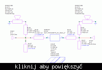

can u tell how should the layout look like , i v got it like this , (other than connections what major changes you propose.)
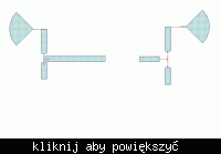
plz .waiting for reply .
 

Re: LAyout for microstip line based microwave amplifier circ

Where is your transmission line discontunities? You should use junction elements between the transmission lines where they connect eachother.
 

Re: LAyout for microstip line based microwave amplifier circ

do I put the juntion between the radial stub and adjacent transmission line as well.
.................. plz
 

Re: LAyout for microstip line based microwave amplifier circ

Hi !
Can any one look at the layout and let me know what changes I need to make, where I need to do via , and how to do that. plz . .
 

Status
Not open for further replies.

Part and Inventory Search

Welcome to EDABoard.com

Sponsor

Back
Top