Vermes
Advanced Member level 4

The following simple electronic system acts as JTAG for Atmega microcontrollers. It uses RS232 port. Because this port is rare in computers, another version of the project using USB was designed.
Build your own AVR JTAG ICE clone | Scientific, embedded, biomedical, electronics contents.
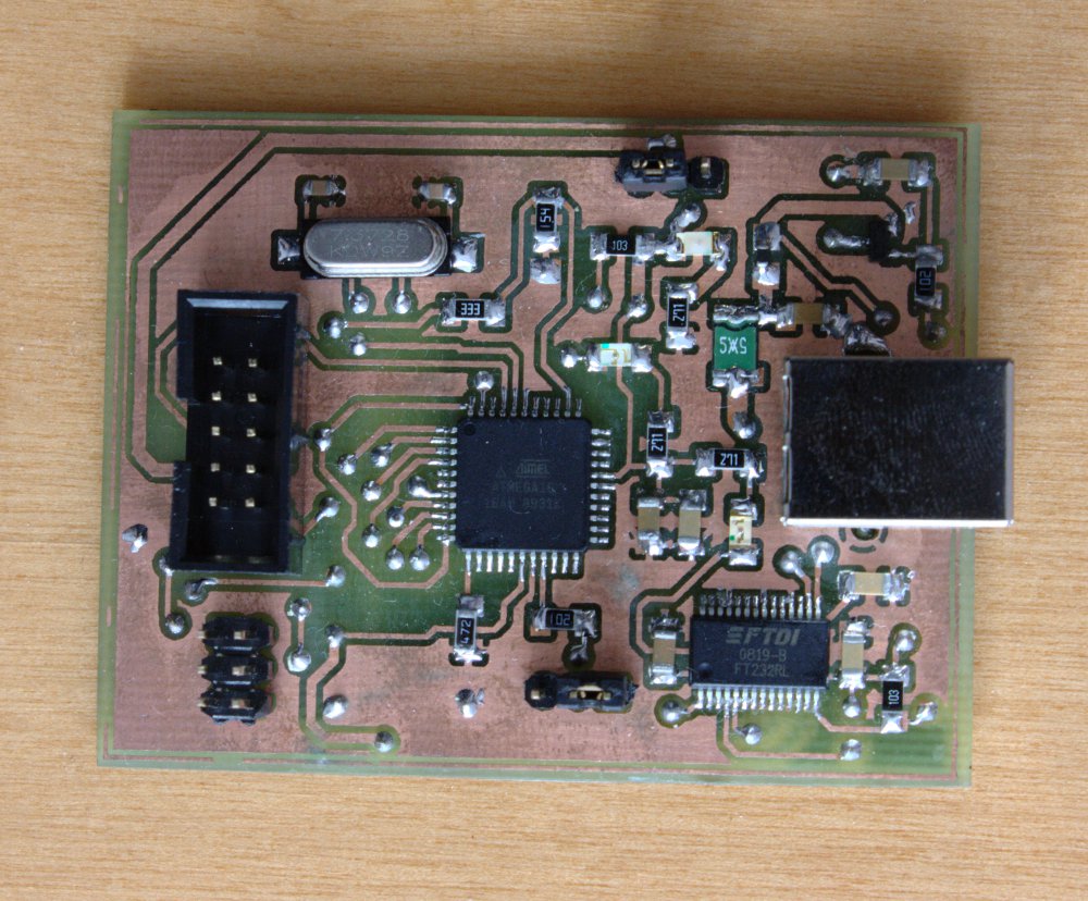
J3 connector was added to Atmega16. It is used for uploading firmware and MAX232 was replaced with FT232RL. Automatic power switch in the form of transistor T1 with soft start circuit (R1, C5) were used. USB specifications takes into account different modes of supply and devices using this bus should approximately limit their current. A transistor controlled by the signal PWREN# (here: CBUS3 leg) was applied. If necessary, the transistor cuts off the power and the whole goes to sleep.
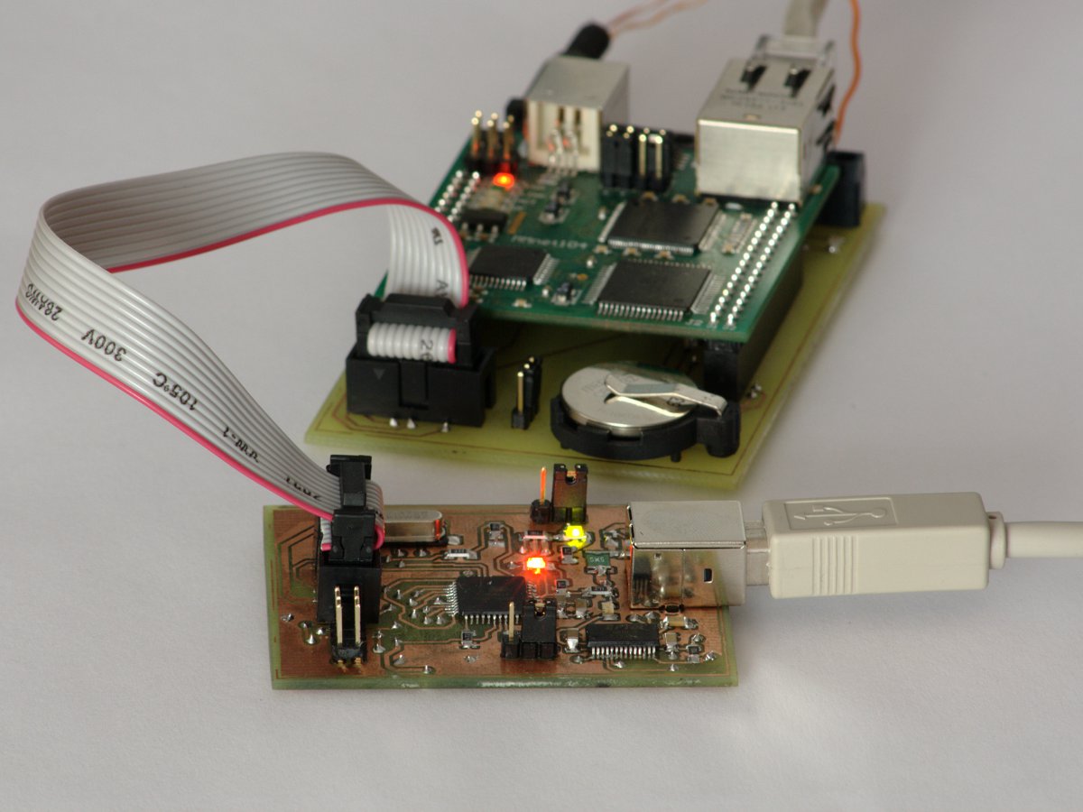
Diodes D1, D2 and D3 may be helpful in diagnosing problems with JTAG. D2 informs that the USB port gave the power, D1 – that there is communication with the computer and D3 – information about working the JTAG interface.
Assembly and start
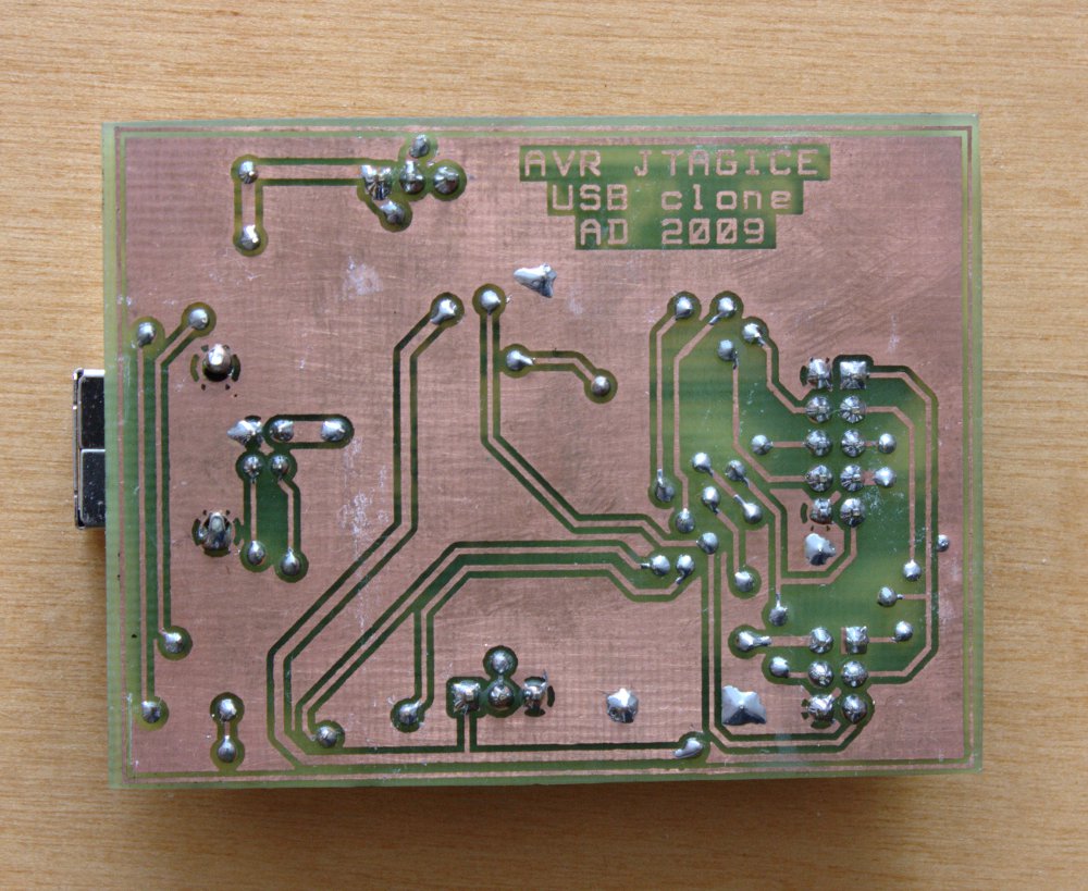
The PCB was designed to be made in home conditions. While assembling, pay attention to FT232RL system. It is made on relatively small pitch, and it is worth to use a flux (e.g. RF800) while soldering. On the USB_Config_Descriptor checker Bus Powered, USB Remote Wakeup and Pull Down IO Pins in USB Suspend and the value Max Bus Power should be set 500mA. The name of the device in USB_String_Descriptors can be set arbitrarily. On the Hardware_Specific -> IO_Controls set the pin IO function:
- C0: TX & RXLED#
- C3: PWRON#
Then, set the jumper J5 in position PROG, program the Atmega and upload the firmware as described in the original version of the device.
After uploading the firmware, set the jumper J5 in the WORK position, and J4 as needed – USB PWR, if debugged system is to be powered from the USB port or DEVICE PWR, if it has its own power supply. JTAG is now ready for use.
After checking the correctness of the assembly, the device can be connected to the USB port. Then FT_PROG should be started and the program FT232RL configured.
Link to original thread (attachment) – JTAG do ATmegi w wersji USB