Vermes
Advanced Member level 4

- Joined
- Aug 2, 2011
- Messages
- 1,163
- Helped
- 0
- Reputation
- 0
- Reaction score
- 0
- Trophy points
- 1,316
- Activity points
- 22,318
You can use the device presented in this project when you need at least two synchronized low frequency generators. The range of tuning in this case is up to 100Hz at a resolution of 0,01Hz. Atmega fulfills this task without any problems. With appropriate software, it can generate such frequency using hardware PWM. The standard (basic) version of the device consists of model generator 16,384MHz that drives the processor, 5 buttons connected to port C and LCD display 2x24 connected to port B. In addition, there are two stabilizers, few passive components. As you can see in the schematic, in order to achieve greater output current, the design uses a current amplifier/ buffer on LM324 and transistors, although the transistors are not necessary. In this basic version, there are three generators. Software allows the tuning with step 0.0019230769231Hz and the selection of shift of phase 8bit, selection of shape of generated wave and also 8bit PWM. In the processor, you can store up to 7 settings of generators, switched by one button.
More developed version is improved with converter CA DAC6571. It is controlled separately by ports twi of the processor with about 768kHz. The equipment sends data without waiting for confirm, so that the DAC can operate with full frequency DDS/ sampling 32.768kHz. Due to the fact that the DAC is 12bit, in order to fulfill the not used resolution, the program allows to change the amplitude of generated signal /2 /4 /8. It can be useful in certain applications, because usually such generators are not equipped with adjustable amplitude. The schematic in block DAC of GEN4 includes potentiometers and operational amplifier that can provide modulation signals for generator 7.
Another version uses hardware DDS. You need boards and AD9833. To improve the quality of signal, they work with clock 32.768MHz (used ICS502). Program allows you to retune these generators with minimal possible step about 0,1Hz and phase shift with a resolution of 12bit (4096 steps). You can also select the shape of generated signal but with some limitations associated with the speed of buffers used.
In ever more extended version you can make 200MHz out of 10MHz using multipiers. Program allows the multiplication of frequency of generators 5 and 6 by values of the range from x4 to x25. Since generators DDS step is equal 0,1Hz, the resolution of retuning is still very high. The device uses PCD8574 and I2C bus for control over the degree of multiplication. At the multipliers output there are emitter repeaters (but they are not necessary). If you decide to use them, they will provide easier change of possibly broken transistor than SMD on a prototype board, as well they ensure fitting 50ohm. You can also get buffered and not multiplied signal of generators 5 and 6 of standard 5V TTL from ICS502.
You can also gain better spectral cleanliness of the signal by using a TV head with generator and a synthesizer. Probably the most problematic thing about it is “provide” the signal which passes to the synthesizer (here: TSA5523M) and the software in processor. High frequency signal is taken from the triple generator output TDA5737 and the synthesizer inputs using the separator amplifier ERA3. This amplifier provides 20dB of amplification to fit to 50R. After the amplification, value of the signal is equal 10dBm.
The schematic shows the possibility to modulate FM and AM of generator 7. Modulating signal is taken by the potentiometers from DAC of generator 4. As for FM – you have to find where the signal modulates the generator (near the capacitive diodes) and connect the signal there.
As for AM – remember that SNA amplifier modulated by variable voltage 5Vpp does not work linearly in such wide range and achieved signal AM has some significant interference. You can fix it by adjusting the potentiometer and changing the levels of signal gen4, then you achieve acceptable distortions for the value of modulation about 20%. Potentiometer AM here has a double functionality, allowing you both regulation of the modulation depth and the high frequency output signal level.
Then you should add power switches on STT5PF20V (any P MOSFET with resistance of connected channel <0.1R) allowing disconnection of the multipliers and TV head.
The housing, as well as the electronics components, can be obtained from old electronics equipment.
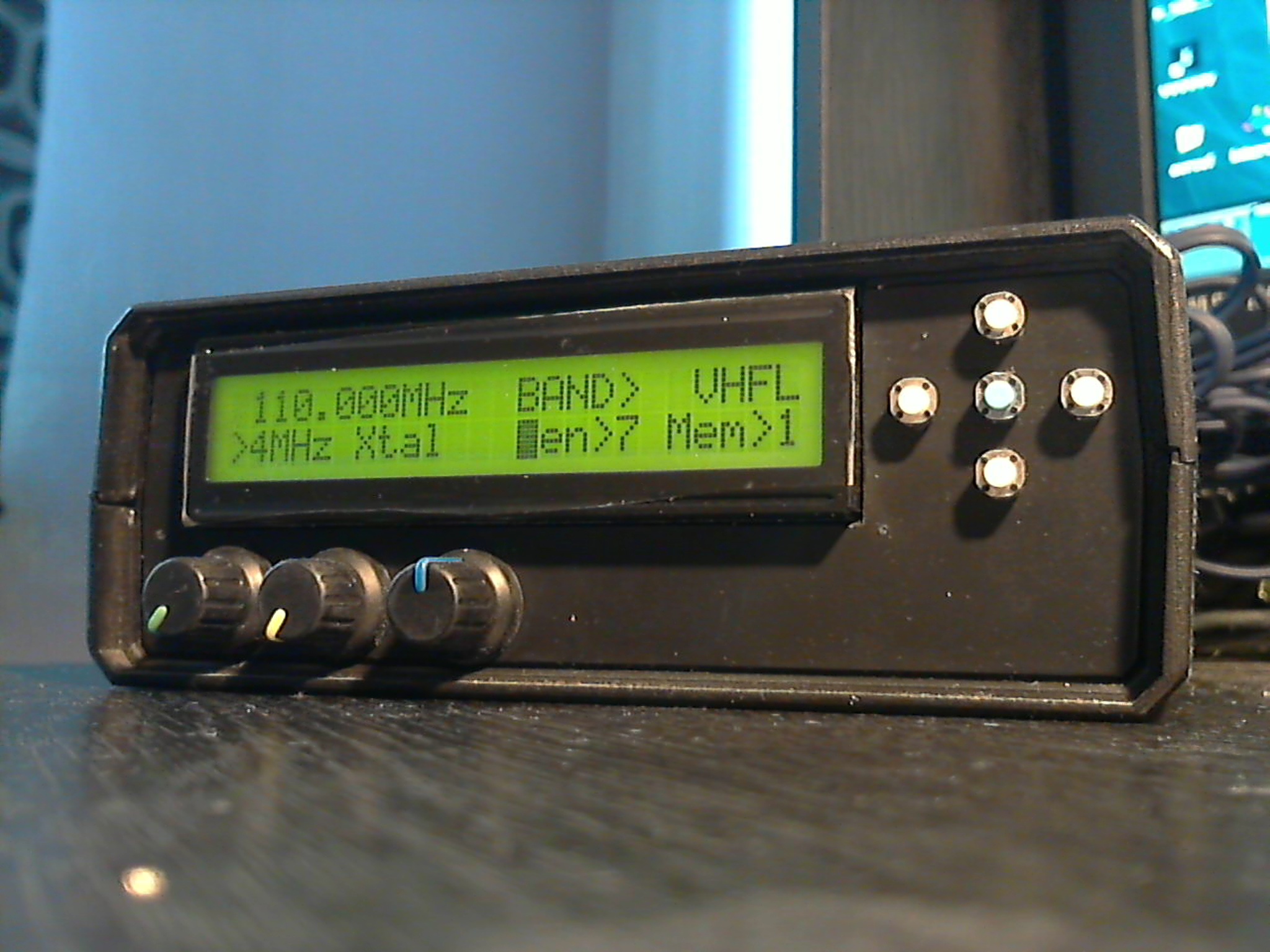
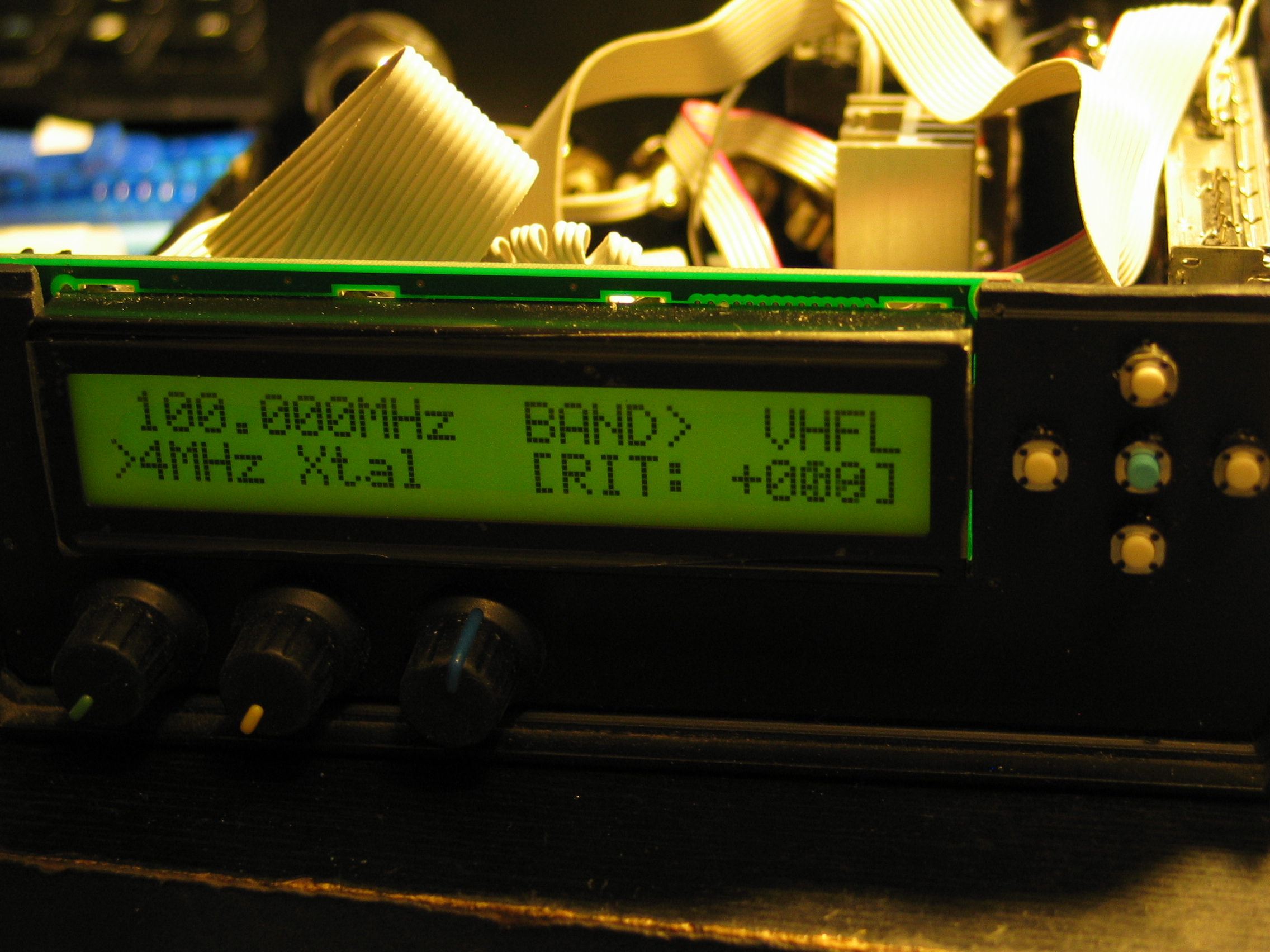
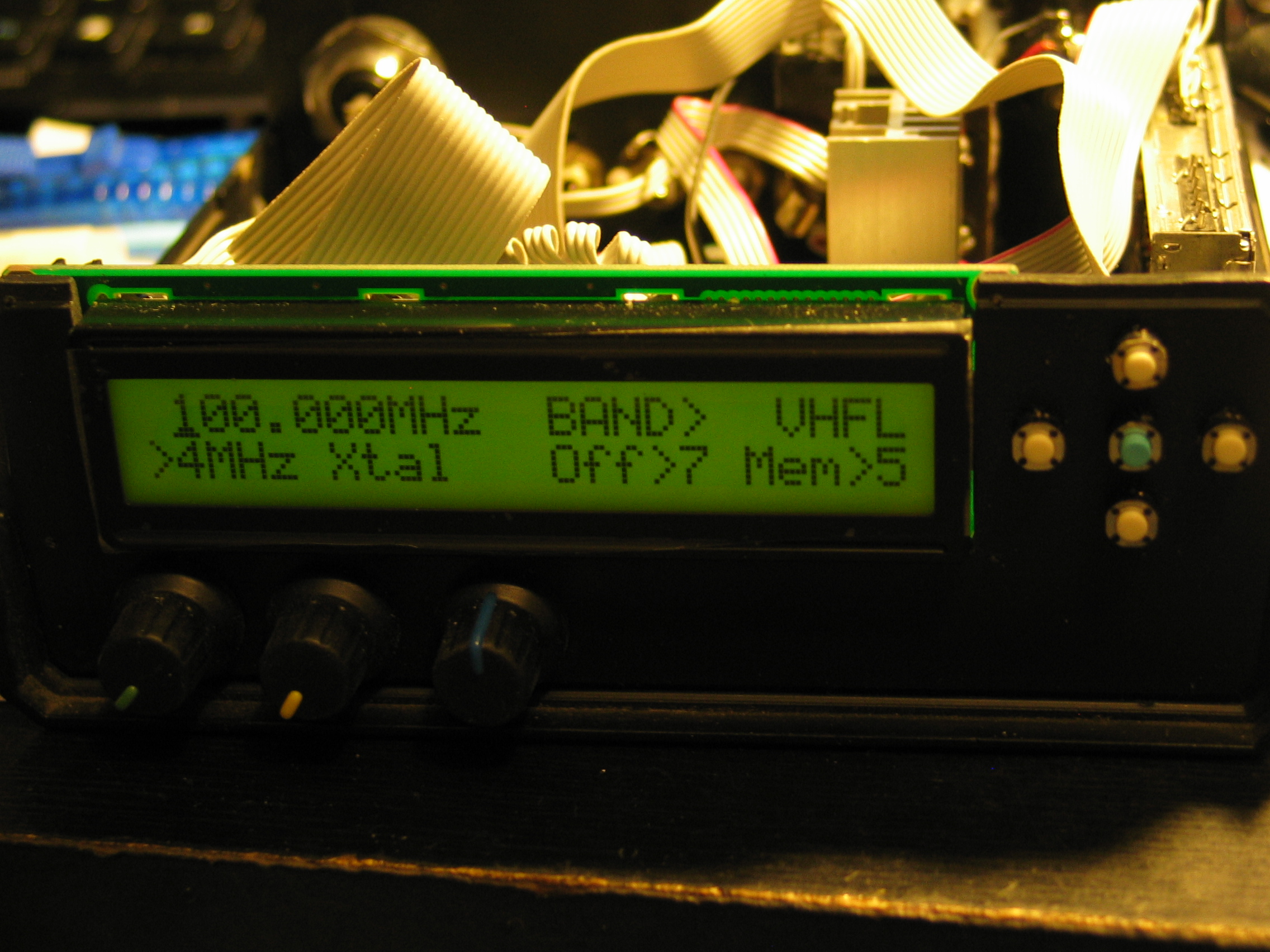
Pictures – front panel with potentiometers FM, AM, RIT:

Back of the device:
Front without the lid:
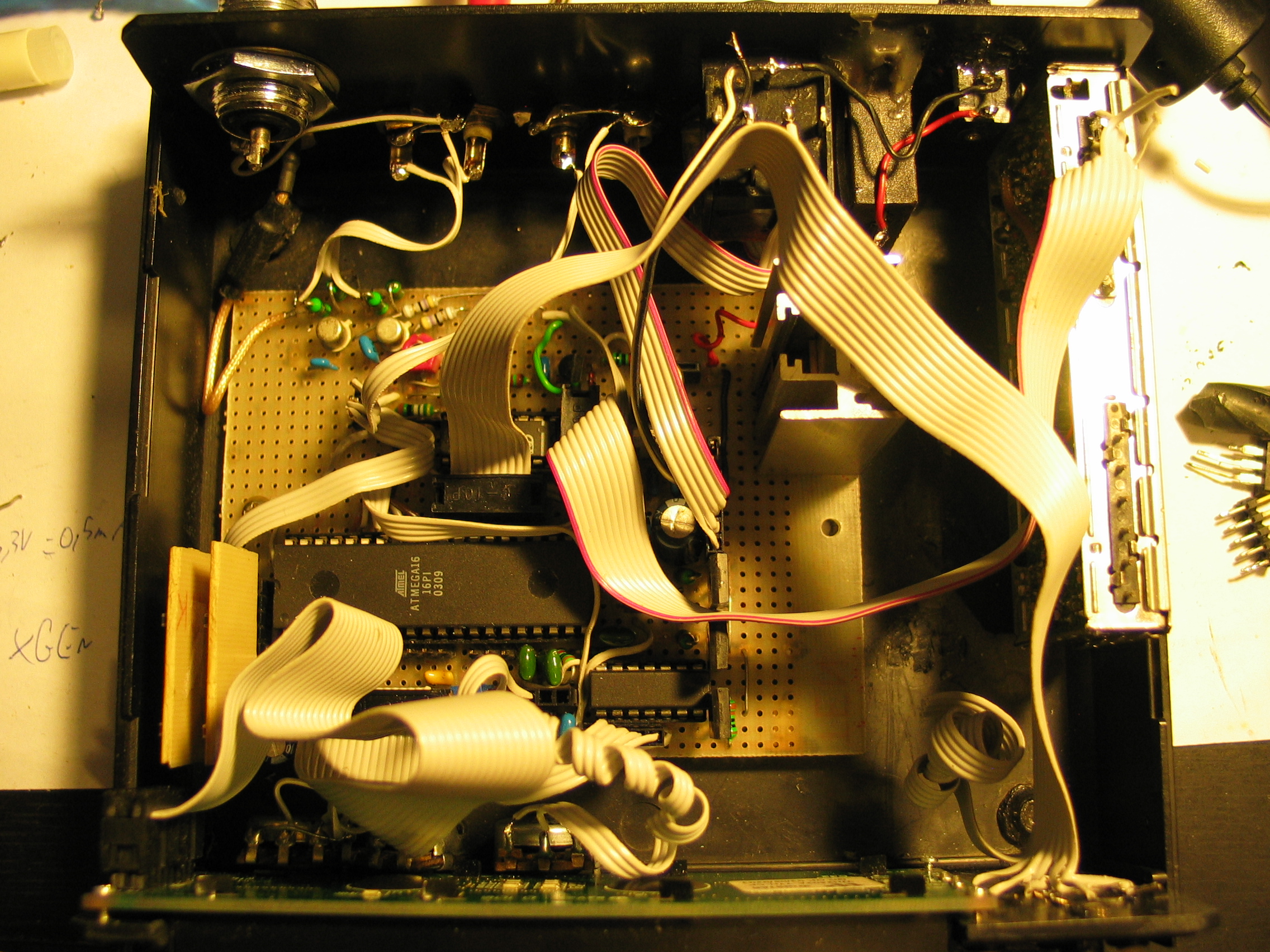
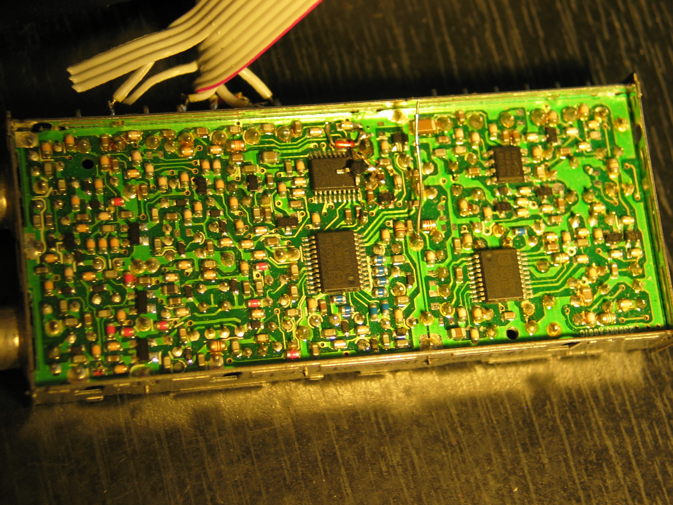
Board with Atmega and cables:

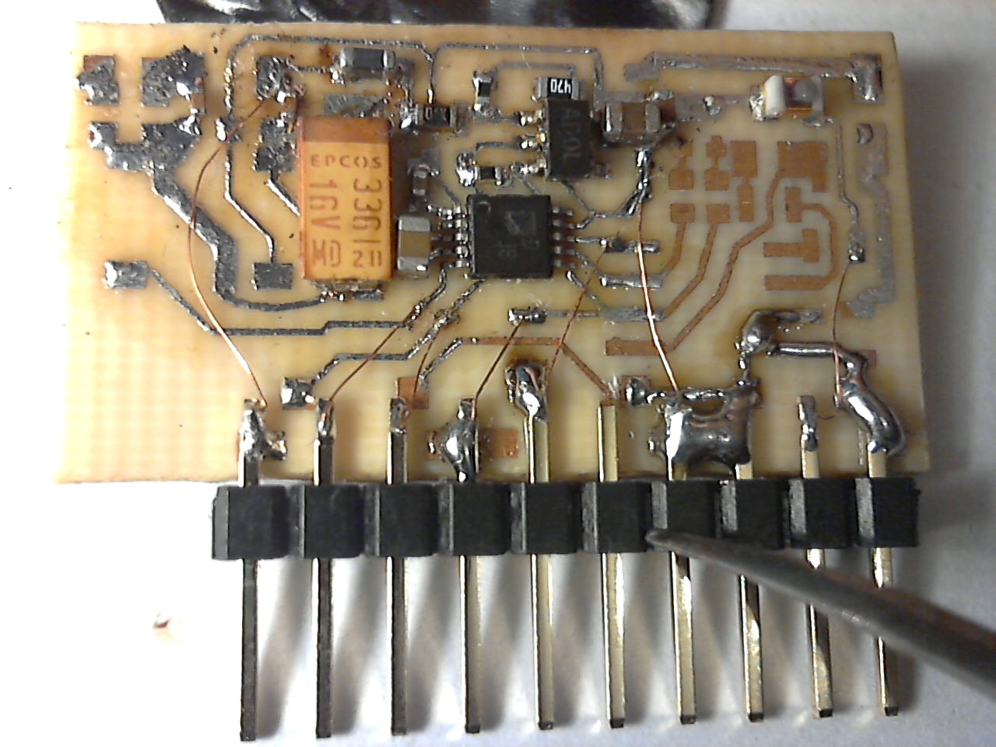
Firsts tests of gaining signal from TV head:
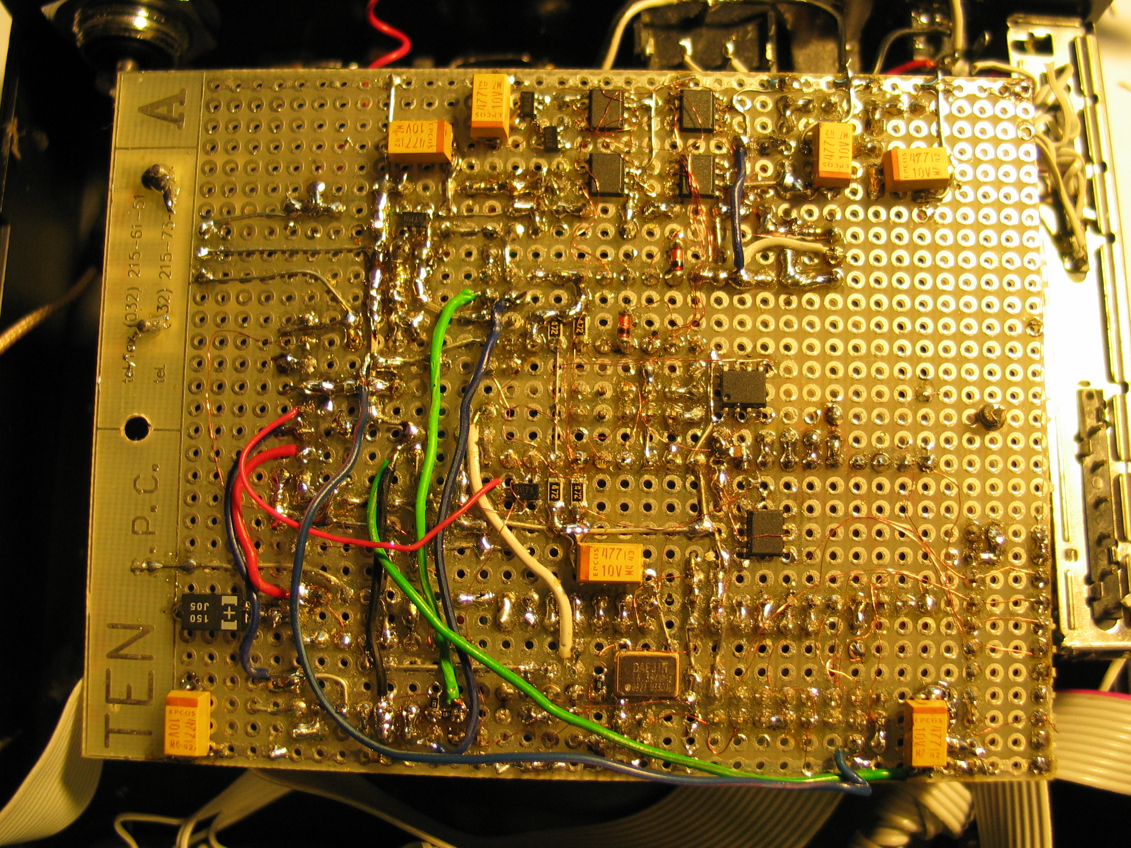
Print of the universal board:
Link to original thread (useful attachment and video) - Generator opcjonalny Megawave Atmega