ElectronicBrain
Newbie level 1
Hi,
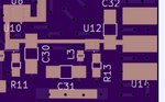
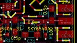
I have designed a PCB for a radar system that is supposed to function at 5.8GHz. The board has been manufactured and populated; however, when I measure the return loss at the return port, I only get 1 or 2dB. Part of the reason appears to be that the capacitors that I used on the RF line (that are used to match the input of the low-noise amplifiers) are too large. However, replacing them with smaller components (without changing the footprint size) has not produced a much better return loss.
As well, I am aware that the SMA center pin pad is much larger than the line; this has been resolved (at least, according to CST Studio) by removing the ground plane and substrate from underneath the center pin pad.
Are there any issues with this section that I am missing that would cause such a terrible return loss?
Thanks.