Continue to Site

Welcome to EDAboard.com

Welcome to our site! EDAboard.com is an international Electronics Discussion Forum focused on EDA software, circuits, schematics, books, theory, papers, asic, pld, 8051, DSP, Network, RF, Analog Design, PCB, Service Manuals... and a whole lot more! To participate you need to register. Registration is free. Click here to register now.

Isolated variable sine voltage in phase with mains?

Status
Not open for further replies.

cupoftea

Advanced Member level 5
Joined
Jun 13, 2021
Messages
2,611
Helped
54
Reputation
108
Reaction score
115
Trophy points
63
Activity points
13,684
Hi,
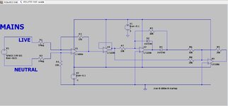
We need a train of precision rectified sines, in phase with mains voltage........but we need it variable in magnitude.

We can do the train of half sines bit (its attached)...but how to make these smoothly variable in magnitude down to zero volts? Variable gain opamps dont seem to exist...we want it variable by putting in a control voltage , say..
....We dont want to use a hand twiddled pot either....because the resolution isnt good enough and the wiper "slips".
This waveform doesnt have to supply any current.
We need approx 1 volt peak....down to zero volts peak...(sorry but you know what i mean!)
 

Attachments

  • isolated sine variable.jpg
    isolated sine variable.jpg
    94.6 KB · Views: 113
  • ISOLATED SINE variable.zip
    1.1 KB · Views: 59
Last edited:

A small mains Tx to provide the isolation, followed by an op-amp with an LDR in the feedback loop, driven by a superbright red LED - the pair contained in a black tube to keep ambient light out, current thru the LED now dictates the gain of the ckt, as the LDR can go from a few 100 ohms to nearly 1Meg - there is plenty of scope for the desired output. ( there is a crowd that makes these too ).

Else a small uP, say a PiC, with a PLL ( or simpler ) tracking the mains zero x-ing, providing variable sine out via a 10 bit D/A ...

By the way the posted ckt would not meet safety standards - esp UL, as you have not specified the R used for the 1Meg, and it is only a single resistor, if it were to develop a short the LV ckt would become a hazard, this is why multiple large resistors are used for such ckts - to reduce the chance of electrocution to near zero if one goes short ( this could be a pcb fault too rather than R failure, or faulty R direct from factory - e.g. mis-marking ).

Also - depending on the op-amp used - if the mains powers up before the Vcc for the LV ckt - ( i.e. switch on at mains peak ) then you may damage the op-amp - inverse parallel diodes across the op-amp inputs ( many have this anyway ) are an added safety for the device.
 
Last edited:
Status
Not open for further replies.

Similar threads

Part and Inventory Search

Welcome to EDABoard.com

Sponsor

Back
Top