Continue to Site

Welcome to EDAboard.com

Welcome to our site! EDAboard.com is an international Electronics Discussion Forum focused on EDA software, circuits, schematics, books, theory, papers, asic, pld, 8051, DSP, Network, RF, Analog Design, PCB, Service Manuals... and a whole lot more! To participate you need to register. Registration is free. Click here to register now.

is theire noise in relay operation?

Status
Not open for further replies.

tapu

Full Member level 5
Full Member level 5
Joined
Sep 15, 2014
Messages
246
Helped
1
Reputation
2
Reaction score
2
Trophy points
1,298
Location
india
Visit site
Activity points
3,164
Dear All,
I am controlling electric bell by microcontroller 89c52 in alarm clock project.here I am using 5vdc relay to switch the bell.During Relay operation can noise be generated? & affects digital operation.& I have to use optoucopler like 4n35?
 
Last edited:

Yes, electromechanical relays produce enormous voltage spikes. That's why there is always a flyback diode connected across the relay coil. No, you don't have to use an optocoupler, you just have to be aware of the voltage spike created when the relay is de-energized, and design accordingly; e.g. route the relay connections away from everything else; use that flyback diode, etc.
 

Yes, electromechanical relays produce enormous voltage spikes. That's why there is always a flyback diode connected across the relay coil. No, you don't have to use an optocoupler, you just have to be aware of the voltage spike created when the relay is de-energized, and design accordingly; e.g. route the relay connections away from everything else; use that flyback diode, etc.

Also there is a problem with contact bounce. Depending on the load this can wreak havoc on your power supply that could affect your controller. There are devices called "transorbers" that deal with that problem. One part number I can recall is VLA130 buy General Electric. Part number might be incomplete. Itis also called a metal oxide varisistor. On the AC power line it is a high resistance until a particular voltage is reached and then becomes a low resistance for a short period of time. More information can be found in websites that sell electronic parts commercially like Digi-key.
 
I am using 5vdc relay to switch the bell.During Relay operation can noise be generated? & affects digital operation

As much as possible you must to work with different 5Vcd power busses, one for power devices, other for digital devices and another for analog devices.

If it s not possible, depending on the switching rate of relay during operation, for much cases at least a simple RC net can suffice for damp the spike caused for the commutation.

Particularly for relays, you also need to keep the tracks on layout design apart from others to avoid electromagnetic induction.
 

Thank you for replies. Here I switch on relay for 3 seconds per hour.That means switching rate is low.I think this will not cause problom.Is it right?
How much distance we should keep from relay to digital circuit to avoid induction?
 

That means I can't use same power supply for controller & relay circuit.here I have to use dual output transformer.is it right?
 

You can use same p/s. But some protection will also be needed. Show you fully schematics and we will suggest you what to do.
 

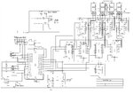
Here is my schematic.

zak1.jpeg
 
Last edited by a moderator:

The design is good enough from the relay perspective. I would suggest to add a small capacitor at the base of Q1 after 4k7 resistor to avoid inadvertent noise triggering the relay. The flyback diode will not suppress the spikes, it actually functions when the relay is turned off and the back emf gets generated. Without the diode, the transistor will get damaged.
From the noise suppression and isolation point of view, the placement of the relay on PCB has to be done properly. The AC lines should not cross with any other analog/ digital lines and also avoid routing any traces very near and under the relay component.
 

You can also use SSRs like these to control the bell. These are optically isolated.

https://www.sainsmart.com/sainsmart...v-32v-5a-for-avr-dsp-arduino-mega-uno-r3.html
https://www.sainsmart.com/sainsmart...y-module-board-omron-ssr-avr-dsp-arduino.html
https://www.sainsmart.com/8-channel...oard-omron-ssr-4-pic-arm-avr-dsp-arduino.html

Alternately you can make your own Solid State Relay board (Single relay) using a few handful of components like, SSR, resistors, BC847, LED, connectors.

You can use this SSR. This is the same SSR used in the above 8 channel and 4 channel SSR boards.

https://www.sunrom.com/p/solid-state-relay-ssr-dc-5v-ac-100-240v-2a

This will solve your noise problem.
 
  • Like
Reactions: tapu

    tapu

    Points: 2
    Helpful Answer Positive Rating
Although the insertion of suppression devices in parallel with the relay coil can damp an expressive part of the spike, it is also strongly advisable add devices in series with the power bus for eliminate residual HF components, particularly at this case on what a supply bus is shared with power and digital circuits.
 

SSR's are an option and maybe a good one here if the current is low. But their performance in terms of current capacity is an order of magnitude worse than a similar size relay.

The combination of a cap and diode is a good one for suppressing the noise. You could also add a cap to the base of the transistor so as to slow down its turn on/off which will smooth things out as well.
 

Status
Not open for further replies.

Part and Inventory Search

Welcome to EDABoard.com

Sponsor

Back
Top