Continue to Site

Welcome to EDAboard.com

Welcome to our site! EDAboard.com is an international Electronics Discussion Forum focused on EDA software, circuits, schematics, books, theory, papers, asic, pld, 8051, DSP, Network, RF, Analog Design, PCB, Service Manuals... and a whole lot more! To participate you need to register. Registration is free. Click here to register now.

interpreting transistor datasheet questions

Status
Not open for further replies.

eng_boody

Member level 3
Member level 3
Joined
Nov 27, 2011
Messages
57
Helped
1
Reputation
2
Reaction score
1
Trophy points
1,288
Visit site
Activity points
1,754
hi all,

First Question
---------------
In the hFE-IC curve it's plotted at logarithmic scale (both axis) assuming i can print the graph and measure distances on paper accurately using a vernier caliper how can i convert distances to linear values (in details please step by step)

Second Question
------------------
Assuming I Could read the hFE-IC curve and convert it into linear scale, the problem it's specified at 4 volts ... how can i obtain such a curve at 5 volts not 4 volts.

Third Question
---------------
Assuming I will force VCE at 5 volts using a 5volts Regulator to measure VBE-IB curve at 5 volts ...and plot a graph (curve fitting) and get equation for that, the problem is that my lm7805 doesn't supply regulate voltage, it fluctuates +- 0.3 (too large), how could get a very stable 5 volt power supply knowing that am using a transformer and bridge not battery how to solve this problem,


thanks in advance , I appreciate all ur comments and replys
 

You don't need to get real fancy with the verniers.
Just pick the 10^N and 3*10^N points off by eye,
enter the numbers in Excel and replot to whatever
to your heart's content. It's not like any process
controls beta to better than 20% initial anyway,
temperature drifts are worse, so just call "good enough"
good enough.

If this is a high voltage transistor then the beta-vs-Ic
curves for 4V and 5V ought to differ very little. You
ought to find an Early voltage number somewhere that
could give you an idea. A (say) 40V transistor is only
going to narrow the base by a percent or two per volt,
beta follows base width. A "5V" device, you would want
to observe rather than predict.

What you really would like is some time in front of a
semiconductor parameter analyzer. But you can poor-boy
it with a couple of power supplies, DMMs and resistor
substitution if you have the time.

If your 7805 is that unstable, there's something pretty
wrong.
 

1. Converting log graph to linear is learning how to interpolate and remember conversion of 10 log X & 10^X . Find an intercept then estimate the other axis value by using division by 2 or 3.
Is it close to the middle?

Then 10log X=50% so X^0.5=3.2 is the midpoint. Then if not middle, bisect the one log range in half twice, thus if at 25% 10^0.25=1.8 and 75%=5.6. Repeat for 1/3 and 2/3. You don't need calipers to split a gap with your eyes to make it equidistant. You can repeat this as often as you wish. You don't have to use a calculator either if you look at a log graph with high resolution and read the actual value on the scale. When the resolution is poor use the above estimates.

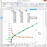
I did the graph of ESR or Rbe in one of your previous questions using eye reading measurements on the graph for V,Ic then noting the graph said Ic/Ib=10, typed the mental result/10 for Ib.

2. Transistors are either used as saturated switches hfe=10 or linear amps. Vce of 4 vs 5 makes little difference in the linear range.

3. Understand that dropout will occur in your LDO if the ripple causes insufficient Vin. Ripple is pure function of the effective load resistance with an RC time slew rate for a period of 1/2 cycle.

Ripple is 50% below the average voltage at rated current and not RMS AC voltage. Since current ripple is not sinusoidal the peak current will be inverse to the voltage ripple. E.g. 10% Vripple implies peak current 10x/2 average current.

The cap value will be inverse to frequency. Thus 100Hz is worst case. 1MHz can use much smaller values per watt of energy storage. Which is why SMPS are preferred.....


Review my Rbe graph again in prev. question. Remember the conclusion. Vbe is just 0.8V for saturation and ESR or Rbe is constant above this. It does not matter what happens on the collector. It can be saturated or linear at Vce=4 or 5V but if current is high, it will fry under this drop. e.g..5W requires heatsink...

so the Vbe saturation vs Ib is the same regardless of Ic and Vce.

Re-read this until it makes sense.
 

i think if y used vernier caliper for y values it will be more accurate .... so please tell me how to do that using vernier caliber .. the problem with me is in setting the scale
 

I contend that if you're trying for better than 20% accurate
using marketing material (datasheet, is that) you are only
fooling yourself.
 

You do not understand that there is no accuracy for the hFE or Vbe of transistors because they have a wide range.
The hFE of a 2N3904 transistor is from 100 to 300 at only one current. The curve in the datasheet is for a "typical' transistor that you cannot buy. Some will have an hFE of 100 and others will have 300 so any accuracy is not there.

The Vbe curve in the datasheet is also for a "typical" transistor that you cannot buy. Some are higher and others are lower.

If you produce many of one circuit then you should design it so it works well if the hFE is high or is low and if the Vbe is high or is low.
 

Everytime you are at cut-saturation use 80% of the minimum hFE. I'm not an engineer but I have ever used that method and I get my circuits working well.

There are several methods to avoid problems with the wide hFE possible value that your transistor can work at, it's common to see a resistor connected to the emitter so the base and collector currents get stabilized.
 

The proper way to do any design is to use both worst case and typical electrical (functional) and mechanical (heat) over the entire operating temperature range. There are no shortcuts to avoiding this. Statistical distribution may be considered in test, if production yield is at risk.

The designer may choose to use nominal and with experience add margin to ensure a reliable design or if necessary choose part numbers from suppliers that sort by bins for hFE such as ROHM Inc.

To help you understand how saturation makes the Rbe fairly constant so that you can predict the room temp Vbe from 0.8V+Rbe*Ibe. I am not sure you understand it was fairly simple for me, but it takes skill or practise.
tip41c~.jpgTip41C_.jpg
I read the 25'C data at 0.1V intercepts and converted Ic tro Ib since this ratio is specified = 10 for saturated mode.
I calculated the incremental resistance or Rbe and plotted in RED with units on the 2nd Y axis while Ibe is on the X Axis.

You could design around nominal but then have to estimate the effects for tolerance & temperature.
 

Status
Not open for further replies.

Similar threads

Part and Inventory Search

Welcome to EDABoard.com

Sponsor

Back
Top