Continue to Site

Welcome to EDAboard.com

Welcome to our site! EDAboard.com is an international Electronics Discussion Forum focused on EDA software, circuits, schematics, books, theory, papers, asic, pld, 8051, DSP, Network, RF, Analog Design, PCB, Service Manuals... and a whole lot more! To participate you need to register. Registration is free. Click here to register now.

interfacing pickit 2 with LM 35 sensors

Status
Not open for further replies.
if you look at the schematic, the demo board already has a potentialmeter connected and the ADC sample code requires connecting the wiper of the pot to RA0.

As to connecting all the Vout pins to RA0, you would only do that if you think connecting different voltages together will allow you to read the voltages individually.
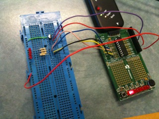
 

can u explain what are this ports 0, 1, 2, 3 to connect the different sensors please and can i read the voltages individually if i connect all the VOUT pins together in same portt
 

can u explain what are this ports 0, 1, 2, 3 to connect the different sensors please

I am happy to but vs. what the datasheet can do, i am totally inadequate on that.
 

ok in LPC r pickit2 which datasheet can explain this and this ports r on the microcontroller r connecting jack
 

I have no idea what you are talking about but I am sure you are right as long as you look into the datasheet.
 

actually im unable to find the information of ports in datasheet so i ask u which datasheet indicates about that
and one more thing u said me tht i can coonect all the vout pins of diff sensors to RA0 is it possible to read all the different voltages saperately and i need some help regarding the program for this LM35 sensor as well please can u help me

Added after 43 minutes:

wp100 said:
Hi,

I assume you are talking about using the 16F690 chip on the starter board.

If so then you will probably be best connecting your 4 sensors to PortC 0,1,2 & 3
These can be used for Analogue or Digital, depending on how you configure them

RA0,RA1 and RA3 are used by the Pickit2 to program the chip, so to keep things simple its better to keep them free for programing.

Are you aware that you can buy different grades of the LM35 - typically the CA and D types which have different accuracy specifications.


by using datasheet i got to know about ports and it's use ok freind u mean to say that i can coonect the multiple sensors to PORTC 0,1,2,3 which and can be used as input ADC im i rite and on track thanks for ur pateince and help still more to shout ok
 

i ask u which datasheet indicates about that

that would be the datasheet for the chip you are using.

i need some help regarding the program for this LM35 sensor as well please can u help me

if I were you, I would focus on being able to read one correctly first. the sample code on the demo board does exactly that so you should get that working first.

after that, you can figure out how to read multiple sensors.
 

helloo i got connections for the sensors just all i need to do is a simple c code to run this circuit so can u please guidee mee to write a code for this LM 35 sensor
 

my offer to you stands: if you get your code to work with one lm35, I will help you get it to work with multiple lm35.

nobody is going to write the code for you.
 

i got the .asm files and program but how do i change it to c so please i am asking help for you can u guide any tutorials atleast how to make changes
 

it is easy:

1) read the datasheet, understand how adc works;
2) read the asm code, understand what it does;
3) implement it in C.
 

You could even throw your asm code away and try it by your self if you have a minimum knowledge of C programming. I would give a little different step-by-step than millwod:

1)Define what you want (something like read the temperature within the range of 0 degree to 100 degree every second and show it on a LCD display)
2)Forget about LM35, just try to learn at you C compiler manual how to handle PIC's ADC.
3)Learn how to display or transmit that information with you C compiler manual.
4)Learn how LM35 works with the datasheet and define how to set the ADC port to better suit your temperature range.
5)Put all toguether, set ADC, sample and display the data.
6)check if the data you are sampling and displaying make any sense. If not you are probably making some mess with you sampled data.
7)Expand to many ADC ports and LM35 sensors.

If you do not have any knowledge of C programing you can try learning it or making it with ASM. C programming is very useful so i would recomend learning it.
 

i must configure PORTA as analogue input, TRISA<0>=1, ANSE:<0>=1 and clock scaling in ADCON1 then channel justification and Vref source in ADCON0

ADCON1 ratio between proceesor speed and conversion speed because ADC need 1.6 microsec per bit
 

i got this code for pic16f690 microcontroller interface so what changes i must do get my output can any one help me out please
Code:
#include <pic.h>
/*  cADC - Display the PICkit Pot Input Value on the built in LEDs

This program samples the voltage on RA0 using the ADC and Displays the 
  value on the 8 LEDs using "cLEDDisp 2" as a base.  

myke predko
04.10.03

*/

__CONFIG(INTIO & WDTDIS & PWRTEN & MCLRDIS & UNPROTECT \
  & UNPROTECT & BORDIS & IESODIS & FCMDIS);


int i, j;
int ADCState = 0;               //  Keep Track of ADC Operation
int ADCValue = 0;
int Dlay = 63;                  //  LED Time on Delay Variable
const char PORTAValue[8] = {0b010000, 0b100000, 0b010000, 0b000100, 
                            0b100000, 0b000100, 0b000100, 0b000010};
const char TRISAValue[8] = {0b001111, 0b001111, 0b101011, 0b101011, 
                            0b011011, 0b011011, 0b111001, 0b111001};
const char NOTPORTA[8] = {0, 0, 0, 0, 0, 0, 0, 0};

main()
{

    PORTA = 0;
    CMCON0 = 7;                 //  Turn off Comparators
    ANSEL = 1;                  //  Just RA0 is an Analog Input

    ADCON0 = 0b00000001;        //  Turn on the ADC
                                //   Bit 7 - Left Justified Sample
                                //   Bit 6 - Use VDD
                                //   Bit 4:2 - Channel 0
                                //   Bit 1 - Do not Start
                                //   Bit 0 - Turn on ADC
    ADCON1 = 0b00010000;        //  Selemct the Clock as Fosc/8

    while(1 == 1)               //  Loop Forever
    {
        for (i = 0; i < 8; i++ )
        {                       //  Loop through Each of the 8 LEDS
            for (j = 0; j < Dlay; j++);  //  Display "On" Delay Loop
            if ((ADCValue & (1 << i)) == 0)
                PORTA = NOTPORTA[i];
            else
                PORTA = PORTAValue[i];
            TRISA = TRISAValue[i];
        }  //  rof
        switch (ADCState)       //  ADC State Machine
        {
            case 0:             //  Finished, Start Next Sample
                GODONE = 1;
                ADCState++;
                break;
            case 1:             //  Wait for ADC to complete
                if (!GODONE)
                    ADCState++; //  Sample Finished
                break;
            case 2:             //  Save Sample Value in "ADCValue" 
                ADCValue = ADRESH;
                ADCState = 0;
                break;
        }  // hctiws
    }  //  elihw
}  //  End cADC
 

that's a good starting point.

a few questions before we move on:

1) are you sure the code works? have you compiled it and run it on your board and consider the behavior to be correct?
2) how many pins does the chip have? how many pins has the code used?
3) of the pins, how many of them can be analog and how many of those analog pins have been used by this code?

through the process, we can identify what pins are available for us to attach your lm35s to.
 

hello

1) when i compile this code i am getting one error which i ll paste it here
Code:
Build C:\Users\masood\Desktop\Code Examples\cADC\cADC.c for device 16F690
Using driver C:\Program Files\HI-TECH Software\PICC\9.80\bin\picc.exe

Make: The target "C:\Users\masood\Desktop\Code Examples\cADC\cADC.p1" is out of date.
Executing: "C:\Program Files\HI-TECH Software\PICC\9.80\bin\picc.exe" --pass1 "C:\Users\masood\Desktop\Code Examples\cADC\cADC.c" -q --chip=16F690 -P --runtime=default --opt=default -D__DEBUG=1 -g --asmlist "--errformat=Error   [%n] %f; %l.%c %s" "--msgformat=Advisory[%n] %s" "--warnformat=Warning [%n] %f; %l.%c %s" 
Error   [192] C:\Users\masood\Desktop\Code Examples\cADC\cADC.c; 30.1 undefined identifier "CMCON0"

********** Build failed! **********

2)it has 20 pins of which code used 8 pins for output as led's and one only input RA0

3)it has 5 analogue pins to be used as input of all which i am using the portA as analogue inputs of lm 35 i have already interfaced this lm 35 sesnors to RA0,RA1,RA2 and the PORTC 0-7 are used as output through led's
 

good progress.

1) you will need to fix that.

2/3) take a look at your code and identify exact which pins are used by the code for the LED output, and compare with the analog pins on your chip to see which analog pins are left unused now.
 

sorry i am unable to fix it as it indicates unidentfied identifier so what may the msitake in that

2/3) RA0 is used as analogue conversion as comparator and the output as led's are connected to PORTC 0-3

this is provided by the hardware but i have interfaced the lm 35 sensors and more 4 led's as ouput through PORTC 4-7 AND PORTA 0-2 as analogue inputs here is the hardware interfaced dgm

85_1282654759.jpg
 

i am unable to fix it

you may not be able to fix it but you have to fix it: before you migrate the code to deal with multiple LM35s, you have to make sure that it works with at least one of them. or you complicate your job.

2/3)the output as led's are connected to PORTC 0-3

is that what your code is doing or that's what you want to do?
 

yes i have fix it now it is working fine and build success and by the way i am pasting the reslut below
Code:
Clean: Deleting intermediary and output files.
Clean Warning: File "C:\Users\masood\Desktop\Code Examples\cADC\cADC.p1" doesn't exist.
Clean: Done.
Build C:\Users\masood\Desktop\Code Examples\cADC\cADC.c for device 16F690
Using driver C:\Program Files\HI-TECH Software\PICC\9.80\bin\picc.exe

Executing: "C:\Program Files\HI-TECH Software\PICC\9.80\bin\picc.exe" --pass1 "C:\Users\masood\Desktop\Code Examples\cADC\cADC.c" -q --chip=16F690 -P --runtime=default --opt=default -D__DEBUG=1 -g --asmlist "--errformat=Error   [%n] %f; %l.%c %s" "--msgformat=Advisory[%n] %s" "--warnformat=Warning [%n] %f; %l.%c %s" 
Executing: "C:\Program Files\HI-TECH Software\PICC\9.80\bin\picc.exe" -ocADC.c.cof -mcADC.c.map --summary=default --output=default cADC.p1 --chip=16F690 -P --runtime=default --opt=default -D__DEBUG=1 -g --asmlist "--errformat=Error   [%n] %f; %l.%c %s" "--msgformat=Advisory[%n] %s" "--warnformat=Warning [%n] %f; %l.%c %s" 
Licensed for evaluation purposes only.
This licence will expire on Mon, 11 Oct 2010.
HI-TECH C Compiler for PIC10/12/16 MCUs (PRO Mode)  V9.80
Copyright (C) 2010 Microchip Technology Inc.

Memory Summary:
    Program space        used    A0h (   160) of  1000h words   (  3.9%)
    Data space           used     Fh (    15) of   100h bytes   (  5.9%)
    EEPROM space         used     0h (     0) of   100h bytes   (  0.0%)
    Configuration bits   used     1h (     1) of     1h word    (100.0%)
    ID Location space    used     0h (     0) of     4h bytes   (  0.0%)

Loaded C:\Users\masood\Desktop\Code Examples\cADC\cADC.c.cof.

********** Build successful! **********

2/3) the code is using PORTC 0-3 AS OUTPUT AND I HAVE STILL PORTC 4-7 AS outputs now i have to set the different led's for different range of temperatures
 

Status
Not open for further replies.

Similar threads

Part and Inventory Search

Welcome to EDABoard.com

Sponsor

Back
Top