Continue to Site

Welcome to EDAboard.com

Welcome to our site! EDAboard.com is an international Electronics Discussion Forum focused on EDA software, circuits, schematics, books, theory, papers, asic, pld, 8051, DSP, Network, RF, Analog Design, PCB, Service Manuals... and a whole lot more! To participate you need to register. Registration is free. Click here to register now.

[PIC] Interfacing PIC24FJ128GC006 microcontroller with Shunt

Status
Not open for further replies.

gravi

Full Member level 2
Full Member level 2
Joined
May 30, 2006
Messages
128
Helped
10
Reputation
20
Reaction score
10
Trophy points
1,298
Location
Hyderabad, India
Activity points
2,451
Hi,

We are trying to interface Shunt 75mV at 500 Amps AD/DC load to PIC24FJ128GC006 microcontroller,

Can we connect shunt directly to Micro controller CH0+ and CH0- pins or do we need any circuit in between. PIC24FJxxxGCyyy series micro controllers have inbuilt 16 bit Sigma delta ADC. So considering the resolution we think that 0.1 milli Volts can also be monitored. But Can you suggest me the best circuit to interface.


Thanking You,
Ravi
 

KlausST

Super Moderator
Staff member
Advanced Member level 7
Joined
Apr 17, 2014
Messages
23,507
Helped
4,758
Reputation
9,537
Reaction score
5,172
Trophy points
1,393
Activity points
155,896
Hi,

A simple schematic would help.

Without it we have to guess.
Shunt is 0.15mOhms. It dissipates about 40W at full load. So i expect you have pulsed load current.
I can´t guess what frequecy and waveform.. so maybe you need an additional sample_and_hold circuit, or your ADC is fast enough to process the data. I doubt a sigma delta ADC in a PIC could do this, but i don´t know.

Then it depends on common mode voltage of the shunt. Is it within the common mode input voltage range of the ADC?

For that low voltages you need differential wiring. This begins with a four wired shunt...

*******
All in all it seems that you may need a fast differential amplifier..

Then you have to decide what you want to do with the converted data.
Calculating average current may be possible, but fast reaction on overcurrent is difficult... usually the sigma-delta ADC has latency time caused by it´s internal filters.

Klaus
 

zsolt1

Full Member level 6
Full Member level 6
Joined
Aug 11, 2012
Messages
367
Helped
50
Reputation
100
Reaction score
49
Trophy points
1,308
Location
Cluj-Napoca, Romania
Activity points
3,880
hi,
I suggest to use low pass filter and unified signal amplifier before feeding the signal to the ADC.
 

gravi

Full Member level 2
Full Member level 2
Joined
May 30, 2006
Messages
128
Helped
10
Reputation
20
Reaction score
10
Trophy points
1,298
Location
Hyderabad, India
Activity points
2,451
Hi,

Then it depends on common mode voltage of the shunt. Is it within the common mode input voltage range of the ADC?

Klaus

Yes, The shunt output is with in the voltage range of the ADC. As suggested by you MCP6292 might be an good choice to interface controller and Shunt. We don't have much information about load. I will probe the Shunt output with a oscilloscope so that that could help us understand the waveform and frequency of the waveform.

Thanking You,
Ravi.

- - - Updated - - -

hi,
I suggest to use low pass filter and unified signal amplifier before feeding the signal to the ADC.

Hi,

Could you please explain better

Thanking You,
Ravi
 

KlausST

Super Moderator
Staff member
Advanced Member level 7
Joined
Apr 17, 2014
Messages
23,507
Helped
4,758
Reputation
9,537
Reaction score
5,172
Trophy points
1,393
Activity points
155,896
Hi,

depending on frequency and estimated precision... the MCP6292 might be problematic:

* +/- 3mV offset
* output swing to rails : 15mV (consider a negative supply. even -100mV would be good)
* GBWP of 10MHz (depending on gain, signal frequency, settling time and precision)

for that high current consider to use hall effect current sensors. Maybe something similar to LEM: FHS 40-P/SP600

Klaus
 

horace1

Advanced Member level 5
Joined
Nov 18, 2008
Messages
2,118
Helped
596
Reputation
1,188
Reaction score
571
Trophy points
1,393
Location
Norwich, UK
Activity points
13,063
also worth looking at
**broken link removed**
 

gravi

Full Member level 2
Full Member level 2
Joined
May 30, 2006
Messages
128
Helped
10
Reputation
20
Reaction score
10
Trophy points
1,298
Location
Hyderabad, India
Activity points
2,451
Hi,

I have gone through Application note AN1332 provided by microchip and hope Three OpAmp Instrumentation Amplifier circuit would meet my requirement. Can I use MCP6294 rather than MCP6H04 Opamp for my application.

MCP6294 is rail to rail Input/Output where as MCP6H04 is rail to rail Output only. Frequency and slewrate are better in MCP6294 when compared to MCP6H04

Thanking You,
Ravi.
 

KlausST

Super Moderator
Staff member
Advanced Member level 7
Joined
Apr 17, 2014
Messages
23,507
Helped
4,758
Reputation
9,537
Reaction score
5,172
Trophy points
1,393
Activity points
155,896
Hi,

Three OpAmp Instrumentation Amplifier circuit would meet my requirement

A single OPAMP differential amplifier is sufficient. But layout is important. Use dedicated sense paths for shunt voltage.
* A three OPAMP instrumentation amplifier has improvements in CMRR, but CMVoltage is fixed in your application
* A three OPAMP instrumentation amplifier has improvements in input impedance, but you have very, very low source impedance.

Klaus
 
  • Like
Reactions: gravi

    gravi

    Points: 2
    Helpful Answer Positive Rating
    V

    Points: 2
    Helpful Answer Positive Rating

gravi

Full Member level 2
Full Member level 2
Joined
May 30, 2006
Messages
128
Helped
10
Reputation
20
Reaction score
10
Trophy points
1,298
Location
Hyderabad, India
Activity points
2,451
Hi Klaus,

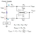
Let us start with an Single OPAMP, I am using the circuit attached and now we are confused how to measure V1 and V2, If I am not wrong they should be measured with the reference Neutral and not with digital ground.

Differential Amplifier.jpg

Thanking You,
Ravi.
 

KlausST

Super Moderator
Staff member
Advanced Member level 7
Joined
Apr 17, 2014
Messages
23,507
Helped
4,758
Reputation
9,537
Reaction score
5,172
Trophy points
1,393
Activity points
155,896
Hi,

Your circuit shows "high side current measurement".

Usually it is easier to use low side measurement. Is this possible?

I don't know what shunt package you are using. Is it SMD, THM, 2 or 4 wire?

*****
If two wire:
Connect the resistor power path. Then connect the sense wires as close as possible at the resitor pads, but opposite to the power connections.
For smd chip resistors i often connect the power path without thermals from the outside. And the sense path i connect with extra wires from underneath the chip. Thm resistors power path on one layer, sense path on another layer.

Klaus
 

gravi

Full Member level 2
Full Member level 2
Joined
May 30, 2006
Messages
128
Helped
10
Reputation
20
Reaction score
10
Trophy points
1,298
Location
Hyderabad, India
Activity points
2,451
Hi Klaus,

I have tested the resistance across Shunt and observed 0.6 Ohms. Also find the image of shunt used,
Shunt Resistor.jpg
 

KlausST

Super Moderator
Staff member
Advanced Member level 7
Joined
Apr 17, 2014
Messages
23,507
Helped
4,758
Reputation
9,537
Reaction score
5,172
Trophy points
1,393
Activity points
155,896
Hi,

Left and right there are two holes each for power path connection.

The two screws are for the sense lines.

*******
Your measurement shows 0.6 Ohms, but the real value is much lower.
It shows that your measurement setup was wrong. Maybe two wire measurement.
Don't make the same mistake with your current measurement.

Klaus
 

gravi

Full Member level 2
Full Member level 2
Joined
May 30, 2006
Messages
128
Helped
10
Reputation
20
Reaction score
10
Trophy points
1,298
Location
Hyderabad, India
Activity points
2,451
Hi,

I am trying with this circuit, Is this correct or any modification required to this.
Current Sense.jpg

Thanking You,
Ravi.
 
Last edited:

KlausST

Super Moderator
Staff member
Advanced Member level 7
Joined
Apr 17, 2014
Messages
23,507
Helped
4,758
Reputation
9,537
Reaction score
5,172
Trophy points
1,393
Activity points
155,896
Hi,

we need to know:
* what is RS_out
* what is RS_In
* Shunt in high side or low side
* ADC input range.

Without the information we need to guess.

Your schematic shows a differential OPAMP circuit with output referenced to VCC.
(i personally don´t like VCC as reference. A reference should be stable, but vcc usually is not that precise)

Klaus
 

gravi

Full Member level 2
Full Member level 2
Joined
May 30, 2006
Messages
128
Helped
10
Reputation
20
Reaction score
10
Trophy points
1,298
Location
Hyderabad, India
Activity points
2,451
Hi Klaus,

RS - Shunt Resistor, Higher Side current sensing and ADC input range is 0 Volts to 3.6 Volts. and the circuit is an differential Op-Amp.

Thanking You,
Ravi
 

KlausST

Super Moderator
Staff member
Advanced Member level 7
Joined
Apr 17, 2014
Messages
23,507
Helped
4,758
Reputation
9,537
Reaction score
5,172
Trophy points
1,393
Activity points
155,896
Hi,

If all of this is correct, then it may work:
* Vcc is less than 3.6V
* Vshunt (common mode) is less than Vcc
* Opamp has RR input capability
* Opamp has RR output capability
* both shunt connections are in the right order
* Opamp Offset voltage fits to your specifications
* Opamp GBW fits your specifications
* you use a proper PCB layout
* you have clean and stable Vcc
....

Klaus
 

gravi

Full Member level 2
Full Member level 2
Joined
May 30, 2006
Messages
128
Helped
10
Reputation
20
Reaction score
10
Trophy points
1,298
Location
Hyderabad, India
Activity points
2,451
Hi,

I am able to sense output with +/- 2.5 mV, is it possible to minimize that error.
When no load is connected I could see 5mV - 6mV is measured by micro controller but when I measure with multi-meter I could find "0" Volts. Can we remove this 5mV or 6mV at no load condition.

Thanking you,
Ravi
 

KlausST

Super Moderator
Staff member
Advanced Member level 7
Joined
Apr 17, 2014
Messages
23,507
Helped
4,758
Reputation
9,537
Reaction score
5,172
Trophy points
1,393
Activity points
155,896
Hi,

Opamp tyjpe, gain, wiring ar the parameters fir offset. I don't know even obe of them

*****
Usally a fixed true offset is no problem for a microcontroller system, because to correct this you just need to subtract the offset in software.

Klaus
 

gravi

Full Member level 2
Full Member level 2
Joined
May 30, 2006
Messages
128
Helped
10
Reputation
20
Reaction score
10
Trophy points
1,298
Location
Hyderabad, India
Activity points
2,451
Hi,

The output with the circuit I used is not satisfactory so I have been working for other better solutions and I have seen few dedicated IC's INA210, INA226 from TI,

The INA210, INA211, INA212, INA213, INA214, and INA210) that can sense drops across shunts at common-mode voltages from –0.3 V to 26 V, independent of the supply voltage. Five fixed gains are available: 50 V/V,75 V/V, 100 V/V, 200 V/V, 500 V/V, or 1000 V/V.

what exactly is this 50 V/V,75 V/V, 100 V/V, 200 V/V, 500 V/V, or 1000 V/V.

Thanking you,
Ravi.
 

KlausST

Super Moderator
Staff member
Advanced Member level 7
Joined
Apr 17, 2014
Messages
23,507
Helped
4,758
Reputation
9,537
Reaction score
5,172
Trophy points
1,393
Activity points
155,896
Hi,

if you encouter problems, then it is most probably a wiring problem than can´t be solved with new circuits.
You didn´t tell what input signal you expect. Without that information we can not give advice what amplifiers to use.

"The output is not satisfactory" is no error description. As long as we don´t know in wich way it is not satisfactory we can not assist you in this.

50V/V = gain of 50. 1V input --> 50V output (theoretically. Look for output voltage range).
It is more: 1mV input 50mV output.

Klaus
 

Status
Not open for further replies.

Similar threads

Part and Inventory Search

Welcome to EDABoard.com

Sponsor

Top