Continue to Site

Welcome to EDAboard.com

Welcome to our site! EDAboard.com is an international Electronics Discussion Forum focused on EDA software, circuits, schematics, books, theory, papers, asic, pld, 8051, DSP, Network, RF, Analog Design, PCB, Service Manuals... and a whole lot more! To participate you need to register. Registration is free. Click here to register now.

[SOLVED] Interfacing a 25 Pin Serial Analog Output to a BNC connector

Status
Not open for further replies.

fubag

Newbie level 3
Joined
Nov 2, 2012
Messages
4
Helped
0
Reputation
0
Reaction score
0
Trophy points
1,281
Activity points
1,307
Hi Guys,

We have a research team that wants to interface an old Datex Ohmeda Capnomac Ultima to a Powerlab BNC monitoring device. capnomacultima_serial_pinout.PNGPowerlab1630front.PNG

Can someone help me figure out how I can get certain output ports connected to the input of the BNC? Or guide me in the right direction?

Appreciate it!
 

The picture shows how to do one hookup. (It does not necessarily show the correct pins to solder to.)

The pins of the D-sub 25 are numbered. You must determine which pins need to be connected to the BNC plug.

You will connect a ground wire and one other (analog) wire to the BNC plug.

There is a difference between analog ground (pin 1) and signal ground (pin 7).
Pin 7 is normally for computer (digital) communication.
I believe you will use pin 1 as ground for your BNC plug(s).

If the wires need to be long, then it may be a good idea to use shielded cables.

If you need to connect multiple wires to the analog ground (pin 1), it can get unwieldy. Try not to heat it more times than you have to. Consider soldering a length of wire to it, and solder other wires to that. Tape it all up to prevent short circuits.

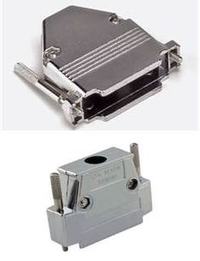
To keep the wiring protected, the D-sub comes with a housing which you attach. Examples are in the photo:


thank you sir!
 

will the bnc twisted pair adapter will it fit in this machine? is it female/male I'm not too sure
Powerlab1630front.PNG
 

Attachments

  • capnomacultima_serial_pinout.PNG
    capnomacultima_serial_pinout.PNG
    49.9 KB · Views: 162

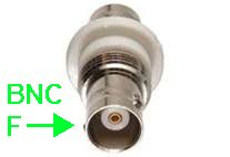
Female BNC. Typical appearance of the connector on equipment.

7143086100_1352152137.jpeg


An internet search brought up this photo of a twisted pair adapter.

It appears there are two holes where you insert the wires. The other ends of the wires will go to the D-sub 25. This may be a convenient way to go, because the male BNC connector can be a puzzle to assemble and disassemble.

I have not used such an adapter. It is labelled 'balun' which may or may not be essential to carrying your signals.

5323671800_1352152225.jpeg
 

Status
Not open for further replies.

Part and Inventory Search

Welcome to EDABoard.com

Sponsor

Back
Top