Continue to Site

Welcome to EDAboard.com

Welcome to our site! EDAboard.com is an international Electronics Discussion Forum focused on EDA software, circuits, schematics, books, theory, papers, asic, pld, 8051, DSP, Network, RF, Analog Design, PCB, Service Manuals... and a whole lot more! To participate you need to register. Registration is free. Click here to register now.

insulation track circuit

matrino

Newbie
Joined
May 7, 2024
Messages
4
Helped
0
Reputation
0
Reaction score
0
Trophy points
1
Activity points
38
Hi,

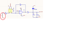
I'm encountering an issue with a circuit (which I've attached to this post). In this circuit, I'm trying to measure the resistance of the component indicated by the red circle. However, I'm facing a problem. I'm using an STM32G030F6P microcontroller to measure the voltage at the node labeled IZO_POS using an ADC pin.

When the resistance is under 100 kohms, the deviation of the measured resistor value increases, which isn't acceptable for this project. For instance, when I use a 10 kohm resistor, I typically read values between 15-20 kohms.

When the resistance is over 100 kohms, I observe a 20% error, which tends to underestimate the real value.

Can you suggest a solution to this problem? Your assistance would be greatly appreciated.

Also, just to provide more context, the 2.5 volts come from a TL431, and the op-amp being used is an LM358 in surface mount device (SMD) form.

Additionally, this circuit will be used to track insulation leakage in electic car.
 

Attachments

  • izo_circuit.png
    izo_circuit.png
    34.4 KB · Views: 42
Hi,

I recommend to use a simulation tool.

****
Please craete a table where we can clearly see the problem:
R_t | expected_U1A_out | measured_U1A_out | expected V_ISO_POS | measured V_ISO_POS | expected_ADC_value | measured ADC_Value

The table should include "good" values as well as "bad" values
(you could keep the effort low by using Excel to automatically calculate the expected values)

Klaus
I Actual values and measured values are like this. 10kohms have very bad measurements.
1715185946205.png
 
Hi,

this is not what I asked for.
With your table I can not locate the cause of the error.

Klaus
 
Nominal U1A output of the shown circuit for R_t range of 10k to 1M is 3.75 to 5 V, all outside STM32 ADC voltage range with forward biased schottky diode. I suppose the schematic doesn't show the real circuit.

Whatever the actual circuit is, the table shows that present measurement value variance is too large to determine R_t accurately.
 
all outside STM32 ADC voltage range
with 3.75V output at U1A ... due to the 1k/1.5k resistive divider .... I expect 2.25V at the ADC input .. which should be fine.

But everthing has it´s limits .... thus my task for the OP to write the table ....
So we - and in best case the OP - can find out if there is a cricuit problem, a "wrong expectation" problem, a mathematical problem, or a software problem ...

Klaus
 
You are right, I overlooked the divider. I appreciate your approach to break down the problem into detail measurements. However post #3 sample variance already shows a serious problem of the test setup.
--- Updated ---

Comparing the variance of low R_t and high R_t measurements suggests that we see picked up noise at the input node (50 Hz hum or whatever is present in the circuit vicinity) in addition to ADC and OP noise. As these error sources can be possibly eliminated by suitable ADC sample filtering, we also need to know how ADC samples are processed.
 
Last edited:
Hello,
First of all, thank you very much for your answers. The diagram here is just a part of the project, but basically the circuit is this. I wrote the materials used in the first post for clarity. My measurements today showed that the problem might be caused by the reference (2.5 v). So, according to my calculations, a small deviation in the reference corresponds to a very large deviation in the ADC pin. So I'm considering replacing the reference TL431 with a better equivalent. This may not solve the problem on its own, but it seems to make the measurements better. If the problem persists after I try the required material, I will write here.
1715267958661.png
 
To measure a linear resistance, inject a small 1uA constant current source and measure the voltage across it from 10mV to 1V for 10k to 1M or 3.3Meg if desired.

Using a Rail-to Rail CMOS OpAmp with << 10mV for offset Vio will work best with a Howland Current source is one method.

1715287022579.png


Your transfer function is non-linear with errors expected. Vout = R atten * Vref*(1+|Av-|)

ISO_POS=R5/(R5+R3)*2.5*(1+R1/(R2+R_t))
1715287194895.png

--- Updated ---

Another method is a high side current mirror using PNP BJT's adjust Rb depending on choice of Vcc and hFE.

1715289979923.png
1715290588727.png
1715290756811.png
 
Last edited:
To measure a linear resistance, inject a small 1uA constant current source and measure the voltage across it from 10mV to 1V for 10k to 1M or 3.3Meg if desired.

Using a Rail-to Rail CMOS OpAmp with << 10mV for offset Vio will work best with a Howland Current source is one method.

View attachment 190684

Your transfer function is non-linear with errors expected. Vout = R atten * Vref*(1+|Av-|)

ISO_POS=R5/(R5+R3)*2.5*(1+R1/(R2+R_t))
View attachment 190685

--- Updated ---

Another method is a high side current mirror using PNP BJT's adjust Rb depending on choice of Vcc and hFE.

View attachment 190686View attachment 190687View attachment 190688
Hi,
Thank you very much for your advice. I will examine it in detail.
 

LaTeX Commands Quick-Menu:

Similar threads

Part and Inventory Search

Welcome to EDABoard.com

Sponsor

Back
Top