Continue to Site

Welcome to EDAboard.com

Welcome to our site! EDAboard.com is an international Electronics Discussion Forum focused on EDA software, circuits, schematics, books, theory, papers, asic, pld, 8051, DSP, Network, RF, Analog Design, PCB, Service Manuals... and a whole lot more! To participate you need to register. Registration is free. Click here to register now.

INL simulation in Cadence

Status
Not open for further replies.

nguyenvanthien

Member level 4
Joined
Oct 31, 2013
Messages
75
Helped
3
Reputation
6
Reaction score
3
Trophy points
1,288
Activity points
1,833
Hi all,
I'd like to simulate INL using Calculator in Cadence. However, I haven't understanded clearly about inl function. Anyone can explain for me. Thanks
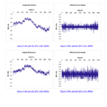
 

When I was using the Calculator (5.1.41), no such function was available, sorry. We had to extract INL as the maximum difference between the received spectrum and the expected linear line, s. Fig. 1b. of this Maxim AN . Represent these curves and try and find the appropriate parameters.

See here INL & DNL result curves for a 10bit ADC: 10bit-ADC_DNL-INL.png
 

Yes, I think the second curve is not correct, but I guess the first one.

Use the Calculator to subtract the ideal normalized curve V(V) = 5V * time(ms)/(256*1.6ms) from the first curve, consider that the result spans 256 LSB, so divide by 256 , this will result in your INL curve.
 
Status
Not open for further replies.

Part and Inventory Search

Welcome to EDABoard.com

Sponsor

Back
Top