Continue to Site

Welcome to EDAboard.com

Welcome to our site! EDAboard.com is an international Electronics Discussion Forum focused on EDA software, circuits, schematics, books, theory, papers, asic, pld, 8051, DSP, Network, RF, Analog Design, PCB, Service Manuals... and a whole lot more! To participate you need to register. Registration is free. Click here to register now.

[SOLVED] Infra Red Object Detection problem

Status
Not open for further replies.

Rajiv ab

Newbie level 3
Joined
Apr 29, 2013
Messages
3
Helped
0
Reputation
0
Reaction score
0
Trophy points
1,281
Activity points
1,319
Hi Greetings,

I have some questions.

I found a Nice Infra red object detection project on a wesite link https://rakeshmondal.info/IR-object-detection i tested it out and its working fine but i am facing some difficulty when i try to make it work with a pic18f2550 microcontroller.

I wrote a small program to input the , output of the IR into the microcontroller .. everything seems to be fine with board but it just dosent work with IR!!!!
In that website its explanied that it can be interfaced to microcontrollers to make it work. In pic i wrote code as such that if RA 1 is provided with logic one from external source then a LED connected accross RD2/spp2 should glow . So when i conencted this IR sensor circuit accross the RA1 and try to glow RD2 nothing happnes. However if i shot a +2v input from the microcontroller itself it works fine,,,, Not working with only this IR.

I feel that i am close but not sure how to do it ... what could be the possible reason ?
 

1.

While you are in the development stage, use a visible led. Since you can't see IR, you can't see whether it is on, or where it is illuminating.

2.

To get a usable signal from the detector, it is typical to hook up a potentiometer in series. Apply a DC voltage across the network. (Never exceed a safe current limit in the network.)

Read the volt level at the node, at different degrees of illumination. Your goal is to find the greatest variation (swing) of voltage.

You may need to amplify this swing, but only the AC portion which is your signal. You must filter out the DC part which is ambient illumination.
 

LM358 O/P will not be the same as Vcc for logic "1" ( but for logic "0" u'll get 0V). If u r powering up the IR ckt with 5V, op-amp logic "1" O/P will not be 5V. near about 3.5V only u'll get. so put one transistor then give it to controller. what's ur controller operationg voltage?


Follow this thread. Instead of LDR u can use IR photo diode (IR Rx LED).

https://www.edaboard.com/threads/286634/#post1226598

While you are in the development stage, use a visible led. Since you can't see IR, you can't see whether it is on, or where it is illuminating.

use ur mobile phone camera or digi cam or any webcam can be used to see IR Light rays. Point IR LED to the camera on the screen u can see the IR light.
 
LM358 O/P will not be the same as Vcc for logic "1" ( but for logic "0" u'll get 0V). If u r powering up the IR ckt with 5V, op-amp logic "1" O/P will not be 5V. near about 3.5V only u'll get. so put one transistor then give it to controller. what's ur controller operationg voltage?
So when i conencted this IR sensor circuit accross the RA1 and try to glow RD2 nothing happnes. However if i shot a +2v input from the microcontroller itself it works fine,,,, Not working with only this IR.


Follow this thread. Instead of LDR u can use IR photo diode (IR Rx LED).

https://www.edaboard.com/threads/286634/#post1226598
Please explain the difference between you suggested scheme and schema which use author the topic?
90027d1366890429-light-sensor.jpg
 

well Mr.pplus, I suggested him that thread for his ref and knowledge. In that thread I have explained 3 different methods. so that one can gain more knowledge about it and can select any one of it based on their application req. I hope u have seen all other ckts too.

Originally Posted by Rajiv ab
So when i conencted this IR sensor circuit accross the RA1 and try to glow RD2 nothing happnes. However if i shot a +2v input from the microcontroller itself it works fine,,,, Not working with only this IR.

I hope he triggered with 2V directly through a short jumper wire. For microcontroller even if u trigger 1V like that is enough to trigger microcontroller will get triggered. As u know its because of spikes & glitches.

pls note this point.
so put one transistor then give it to controller.
so that for logic "0" & "1" it'll give 0V & 5V

View attachment 90029


pls correct if anything wrong in my statement.

if anybody found that any of my post really helped u pls hit helped button (so that I'll b knowing it)
if something wrong in that pls correct immediately (so that I'll be knowing it & I'll guide others in right way)
 

Both schemes are practically identical, differ only resistors supply LED - 1K and 330 ohms. I'll try to explain. On your chart is not listed the type of op-amp, so we assume it also lm358.
8427495500_1367318854.png

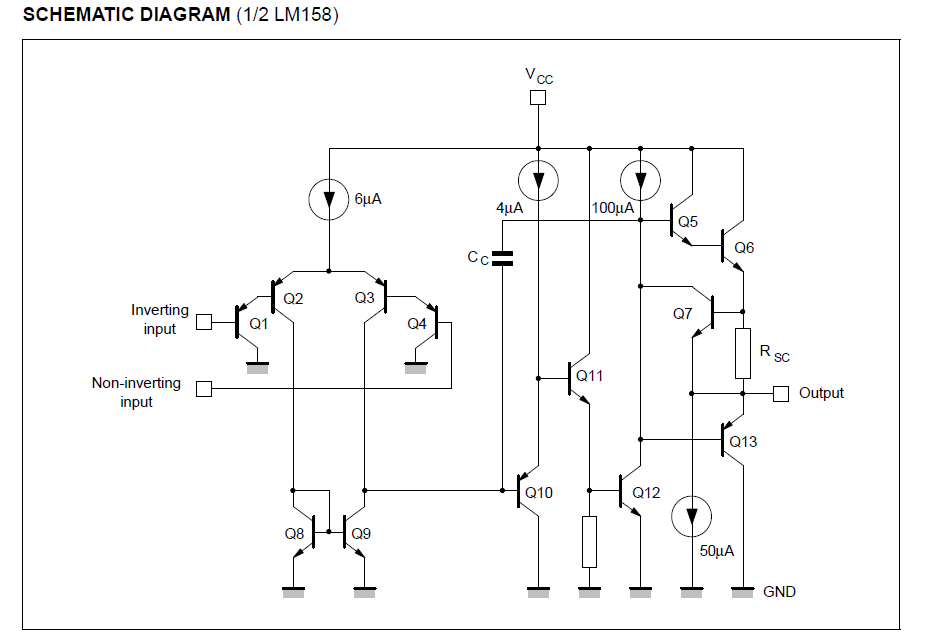
In this op-amp maximum output voltage is limited to a drop across Vsat (Q5,Q6 )+Rsc and is at the manual 1,5V-2V.
Therefore when Vcc = 5V, we can get the output of about 3-3.5V. If you need a higher output voltage of the transistor switch is necessary.
But I think that all is not low voltage, it is the presence of the variable component of the signal or the self-excitation of the operational amplifier.
 

I have some doubts,

Both schemes are practically identical

which two scheme u r comparing?


But I think that all is not low voltage, it is the presence of the variable component of the signal or the self-excitation of the operational amplifier.

can u explain this statement pls.
 
The schematic linked in post #1 doesn't even manage to connect the LM358 power supply. I don't expect that it's good for anything.
 

The schematic linked in post #1 doesn't even manage to connect the LM358 power supply. I don't expect that it's good for anything.

On the schematic linked in post #1 is bottom view . Pins 4 and 8 are connected to supply.


which two scheme u r comparing?
https://rakeshmondal.info/IR-object-detection post #1
signal conditioning circuit for LDR your post #4

can u explain this statement pls.
The variable component of the signal, such as IR 100HZ from the bulb.
 
Thank you so much for such valuable replies . :)

First voltage differnce is not at all a problem. To triger the logic 1 in the microcontroller even 1 v is enough so voltage across the led is not at a problem. I just connected the output of the led to input of microcontroller. But still microcontroller was not reading..

I actually found the solution I did a very very basic mistake ... I just forgot one basic step. I forgot to shot the GND of the microcontoller to the GND of the IR sensor as on https://rakeshmondal.info/IR-object-detection ... hence my mistake :)

After many hours of cracking my head and reading through the post.. I found this very basic mistake, [GND]

And as of now regarding the IR sensor i found on rakeshmondal.info its so far is serving my purpose very well. its chep , easy to make , shot range and i installed few more to my microcontroller to make a combined logic on my microcontrollers and the IR sensor is working like a charm :)
Thank you alll sooo much for posting such nice schematics .,

Any more sugegstions is very much welcome :)
 

Status
Not open for further replies.

Similar threads

Part and Inventory Search

Welcome to EDABoard.com

Sponsor

Back
Top