Continue to Site

Welcome to EDAboard.com

Welcome to our site! EDAboard.com is an international Electronics Discussion Forum focused on EDA software, circuits, schematics, books, theory, papers, asic, pld, 8051, DSP, Network, RF, Analog Design, PCB, Service Manuals... and a whole lot more! To participate you need to register. Registration is free. Click here to register now.

Increase meter sensitivity in frequency to voltage converter

Status
Not open for further replies.

neazoi

Advanced Member level 6
Joined
Jan 5, 2008
Messages
4,122
Helped
13
Reputation
26
Reaction score
15
Trophy points
1,318
Location
Greece
Activity points
36,951
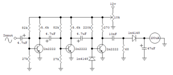
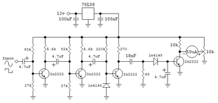
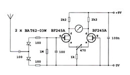
Hi this is a simple audio frequency to voltage converter I have designed with the help of a few members here.
I use it to measure 480Hz-2700Hz tones. 480Hz is the minimum frequency required, below that I do not care.

Now what I need, is to narrow it's bandwidth (i.e. achieve full meter scale by lower maximum frequencies audio tones). One way, is to use a 50uA meter instead of 100uA. This will allow a meter peaking at a lower frequency (around half).
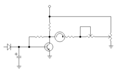
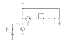
But instead of doing so, I was thinking that I could use an amplifier just before the meter.

The amplifier should detect the different voltage levels on the electrolytic near the meter and drive the meter. This way I could use a higher current meter. Obviously the amplifier should not load the input capacitor too much, so as not to produce erroneous readings.

What do you suggest me to do?
A simple 2n7000 could do the job? or maybe a bjt like 2n2222?
Please suggest me a simple circuit to achieve what I need.

The narrower the bandwidth I can achieve, the better for me. That is full deflection of the meter for only 100Hz or even less.
 

Attachments

  • detector.PNG
    detector.PNG
    8.3 KB · Views: 129

You say you want to narrow the bandwidth, but then you talk about increasing the meter sensitivity, those are two quite different things. And your circuit looks to me to be an amplifier followed by a high-pass filter and then a peak detector with the meter used as a bleed.

Sure, you can just boost the gain and saturate at higher frequencies; you don't need an extra transistor, just change a collector resistor.

Now as it is, the 100uA meter deflects about 15% at 480Hz and 100% at 2700Hz. If I use a more sensitive meter (say 50uA) I could make it deflect double that, 200% (out of range) at 2700Hz and 30% at 480Hz. To bring the maximum deflection back to 100% and the minimum deflection to 15%, I could reduce the high AF frequency to half and still have the previous range of meter deflection (15% to 100%).
This is what I mean by bandwidth reduction.

In that sense, as I increase the meter sensitivity, I can reduce the AF bandwidth required for the same meter deflection (15% to 100%) more and more.
 

Your meter can't deflect 200%. However, you CAN burn out the coil, if you like.

Like I said, just change your collector resistor to increase the output.
 

Its a pulse counting frequency meter. Basically it amplifies the signal to make it 'square' so its amplitude is constant then uses the RC time constant of the 10nF cap and the resistors around it to convert the pulses to sawtooth with amplitude depending on frequency. The final diode then converts the sawtooth back to a measurable DC the meter can use.

You can change the value of the second 10nF cap and the 68 Ohm resistor to shift the frequency range to some degree but not to narrow the range. For that you would have to amplify the current to the meter and apply an offset to set the lowest frequency.

Brian.
 

    neazoi

    Points: 2
    Helpful Answer Positive Rating
For that you would have to amplify the current to the meter and apply an offset to set the lowest frequency.

Exactly. This is why I was thinking of this meter amplifier.

The circuit actually works ok. As long as the input amplitude is more than 10% or so from my sound card output, then no matter if I go all the way to 100%, the reading does not change. This is a very desirable feature.

Can you please suggest me a meter amplifier circuit to try as a starting point? Will a single BJT with the meter connected to the collector, do the trick?

Also this thing about the offset you mention is very desirable, so that I can use the whole meter scale. Can you please suggest me a way to do it? Perhaps somehow bias this final meter amplifier?

Thanks
 

I'm not sure how much gain you will need but the simplest fix I can think of is to use a single bipolar transistor, in common emitter configuration, biased to be linear and with a collector resistor of say 10K. Connect the meter between the collector and the wiper of a potentiometer, the ends of the pot going to ground and supply. Add a fixed current limiting resistor and a 'sensitivity' variable resistor in series with the meter itself.

That should let you 'zero' the meter with the voltage produced by one frequency and still vary the maximum deflection for the other. It might be an idea to wire a small Schottky diode across the meter so it can't pass too much reverse current.

Brian.
 

    neazoi

    Points: 2
    Helpful Answer Positive Rating
I'm not sure how much gain you will need but the simplest fix I can think of is to use a single bipolar transistor, in common emitter configuration, biased to be linear and with a collector resistor of say 10K. Connect the meter between the collector and the wiper of a potentiometer, the ends of the pot going to ground and supply. Add a fixed current limiting resistor and a 'sensitivity' variable resistor in series with the meter itself.

That should let you 'zero' the meter with the voltage produced by one frequency and still vary the maximum deflection for the other. It might be an idea to wire a small Schottky diode across the meter so it can't pass too much reverse current.

Brian.
Like this Brian?
An estimation of the bias base resistor?
 

Attachments

  • Capture.PNG
    Capture.PNG
    3.2 KB · Views: 107
Last edited:

Exactly right. The bias resistor should be just low enough that the transistor starts to conduct when fed with the lowest frequency. Some bias current will come from the diode but you really want to overcome the non-linearity you would expect as it just starts to come into conduction.

Don't forget the diode across the meter because the 'zero' potentiometer will allow the meter movement to work backwards as well as forwards. If you swap the fixed and variable resistors in series with the meter so the fixed one goes to the zero pot, then wire the diode across the pot and meter it will further help to protect the meter against over current. Wiring it this way ensures that the fixed resistor is always in the current path, otherwise there is a (small) risk that if the transistor was fully conducting and the zero pot set to highest voltage and the sensitivity pot set to minimum the diode and meter would fry.

Brian.
 

    neazoi

    Points: 2
    Helpful Answer Positive Rating
Exactly right. The bias resistor should be just low enough that the transistor starts to conduct when fed with the lowest frequency. Some bias current will come from the diode but you really want to overcome the non-linearity you would expect as it just starts to come into conduction.

Don't forget the diode across the meter because the 'zero' potentiometer will allow the meter movement to work backwards as well as forwards. If you swap the fixed and variable resistors in series with the meter so the fixed one goes to the zero pot, then wire the diode across the pot and meter it will further help to protect the meter against over current. Wiring it this way ensures that the fixed resistor is always in the current path, otherwise there is a (small) risk that if the transistor was fully conducting and the zero pot set to highest voltage and the sensitivity pot set to minimum the diode and meter would fry.

Brian.
I have tested the previous circuit and it works!

So here attached with the changes you mention. Is it ok Brian?
 

Attachments

  • Capture.PNG
    Capture.PNG
    3.7 KB · Views: 104

Almost - the anode of the new diode goes to the wiper of the sensitivity control, otherwise it would be possible to set the two potentiometers in such a way that if the transistor became fully conductive the supply would shorted out. You can use two diodes, in parallel but connected in opposite directions, the voltage needed to operate the meter is far lower than they need to reach conduction threshold but if it does exceed about 0.6V the will divert current around the meter so it doesn't get damaged.

Brian.
 

    neazoi

    Points: 2
    Helpful Answer Positive Rating
Almost - the anode of the new diode goes to the wiper of the sensitivity control, otherwise it would be possible to set the two potentiometers in such a way that if the transistor became fully conductive the supply would shorted out. You can use two diodes, in parallel but connected in opposite directions, the voltage needed to operate the meter is far lower than they need to reach conduction threshold but if it does exceed about 0.6V the will divert current around the meter so it doesn't get damaged.

Brian.
Ok here is the circuit, and it allows for 80Hz on full deflection of the 50uA meter.
But, the thermal stability is not good. Just blowing to the circuit (meter transistor, diode and 18nF capacitor) the needle moves quite a lot.
Any ideas how to cope with this is possible?
 

Attachments

  • detector.png
    detector.png
    7.7 KB · Views: 101

I hope you followed my recommendation to limit the meter current in the earlier posts. That schematic in post #12 could very easily damage the meter!

I'm not surprised it has stability issues, this is the reason why this technique isn't used for narrow band F to V conversion. It relies heavily on the components themselves having good thermal stability. Typically pulse counting detectors are used where the frequency shift is tens or hundreds of KHz and the output is AC coupled. You have probably noticed that the meter is also driven backwards if the input signal is removed or out of range.

You can try compensating for the temperature drift and it might improve the results but I doubt you will find a reliable solution. The biggest drift will come from the final diode and transistor, they will both become more conductive as the temperature increases so you could try adding a small diode or two in the ground end of the potentiometer so it drops the voltage on the wiper to compensate. The diode(s) will have to be physically as close to the transistor as possible so they see the same temperature changes.

The other alternative is a bridged meter driver using two transistors so both sides have the same temperature characteristics and cancel each other out.

Brian.
 

    neazoi

    Points: 2
    Helpful Answer Positive Rating
I hope you followed my recommendation to limit the meter current in the earlier posts. That schematic in post #12 could very easily damage the meter!

I'm not surprised it has stability issues, this is the reason why this technique isn't used for narrow band F to V conversion. It relies heavily on the components themselves having good thermal stability. Typically pulse counting detectors are used where the frequency shift is tens or hundreds of KHz and the output is AC coupled. You have probably noticed that the meter is also driven backwards if the input signal is removed or out of range.

You can try compensating for the temperature drift and it might improve the results but I doubt you will find a reliable solution. The biggest drift will come from the final diode and transistor, they will both become more conductive as the temperature increases so you could try adding a small diode or two in the ground end of the potentiometer so it drops the voltage on the wiper to compensate. The diode(s) will have to be physically as close to the transistor as possible so they see the same temperature changes.

The other alternative is a bridged meter driver using two transistors so both sides have the same temperature characteristics and cancel each other out.

Brian.
Ok Brian.
Although tried it, I did not finally use the meter current limiter resistors to have max sensitivity. This will be used to detect tones in a narrow HF mode I design.
I did not try to bias the transistor, as it worked even without a bias resistor. In that small range I did not see any significant linearity problems.
I also tried the diode in the meter circuit but I did not see any effect. The meter still hits back when disconnected.

Indeed the final diode and the transistor has the most thermal effect. I suspect the additional diode from the potentiometer has to be connected from the potentiometer ground pin to the ground, right?

I bet that a bridged meter driver could help, I remember these from the old voltmeters.
Can a simple circuit like this do the trick? How should it be connected to my circuit, just after the rectifier diode? MAybe the diode should be in reverse to produce negative voltage?
--- Updated ---

Ok Brian.
Although tried it, I did not finally use the meter current limiter resistors to have max sensitivity. This will be used to detect tones in a narrow HF mode I design.
I did not try to bias the transistor, as it worked even without a bias resistor. In that small range I did not see any significant linearity problems.
I also tried the diode in the meter circuit but I did not see any effect. The meter still hits back when disconnected.

Indeed the final diode and the transistor has the most thermal effect. I suspect the additional diode from the potentiometer has to be connected from the potentiometer ground pin to the ground, right?

I bet that a bridged meter driver could help, I remember these from the old voltmeters.
Can a simple circuit like this do the trick? How should it be connected to my circuit, just after the rectifier diode? MAybe the diode should be in reverse to produce negative voltage?
Or a BJT one, with the right BJT base connected to the potentiometer? https://diyelectronicsprojects.blogspot.com/2012/08/balanced-bridge-voltmeters-circuit-diagram.html
 

Attachments

  • field_strength_meter_balanced_FET.jpg
    field_strength_meter_balanced_FET.jpg
    37.9 KB · Views: 137
  • voltmeter.jpg
    voltmeter.jpg
    95.2 KB · Views: 96
Last edited:

All I can advise is to try it, as I stated, you are really using a circuit designed for much wider frequency range so the output voltage will be small and suffer the effects of amplification.

It wouldn't make any difference whether you used FETs or bipolar transistors but you should minimize any temperature difference between them by physically bonding them together or placing them in the same insulated environment. Yes, place the pot in the base of one transistor and the final diode in the base of the other.

The idea of the diodes across the meter isn't to stop it deflecting backwards, it is to bypass some of the current if the voltage across it goes too high. That's why I suggested the fixed resistor in series with the meter should be 'inside' the diode connections where it would be more effective.

I suspect the additional diode from the potentiometer has to be connected from the potentiometer ground pin to the ground, right?
Yes, but it should be thermally bonded to the transistor if possible. The idea is that the transistor becomes more conductive as temperature rises so if you can compensate by lowering its bias voltage you can cancel the effect. It will never be perfect because the potential divider formed from the pot will also divide the cancelling effect.

Brian.
 

Just for future work you could do this in a single chip, sub 1 Hz if needed, excellent accuracy,
nada drift, and have lots of other resources as well onchip to do other stuff.

1628092361558.png


What you see above is one chip, right hand window shows resources used/left. As you can see not much
of the chip was used.

Basically an analog front end gains up signal, followed by comparator to yield clean signal of tone to be fed to
Reciprocal freq cntr. That result is then fed to current DAC to drive your meter. Also onboard is VDAC if thats
preferred.

Estimate code at < 25 lines needed.

You could even use onchip dig filter to create very high Q filter for super narrow band detection.

The LCD onchip interface just for debug if sticking with analog meter, otherwise it can be deleted.

Just a thought.

Regards, Dana.
 
Last edited:

Simple frequency-to-V converter.

1) Diodes clip signal to uniform volt level.
2) High pass filter. (Adjust so lowest desired frequency starts upscale reading.)
3) Peak detector. (Adjust for desired linear response and volt range).
4) Amplify output if needed so as to drive a meter.

freq-to-V 480-2700 Hz (high-pass then peak detector).png
 

    neazoi

    Points: 2
    Helpful Answer Positive Rating
That's basically what the first schematic does Brad except it uses a clipping amplifier at it's front end so it can use smaller input signal levels. It will suffer the same problem though, the output voltage variation from one frequency to the other is small so it will need amplification to drive the meter and both the amplifier and filter components will drift with temperature.

I think my approach would be simple frequency counter and a PWM output to set the meter current. Can be done in one 8-pin MCU and a few lines of software. It would give a true reading without drift and the edge frequencies could be changed easily. It also wouldn't risk damaging the meter by excess current or driving it backwards.

Brian.
I tried it.
Two BJTs with their emitters to the ground.
later tried also with emitters connected to the sides of a 1k trimmer, then the wiper connected to the ground.
The base of bjt A, connected to the last diode.
The base of bjt B, connected to the wiper of another pot. The other end of the pot to the GND and the other to the vcc.
The collector of bjt A to a 10k to the vcc and the collector of bjt b, to a 10k to the vcc.
Then the meter connected between the collectors.

I believe I got the bridge right.

It did not make a huge difference in thermal stability. I am curious why though. It is a bridge, it should do...
 

Try linking the emitters together and grounding them through a single resistor (try 1K). The transistors MUST be thermally bonded so any change in temperature has the same effect on both.

Brian.
 

    neazoi

    Points: 2
    Helpful Answer Positive Rating
Status
Not open for further replies.

Part and Inventory Search

Welcome to EDABoard.com

Sponsor

Back
Top