Continue to Site

Welcome to EDAboard.com

Welcome to our site! EDAboard.com is an international Electronics Discussion Forum focused on EDA software, circuits, schematics, books, theory, papers, asic, pld, 8051, DSP, Network, RF, Analog Design, PCB, Service Manuals... and a whole lot more! To participate you need to register. Registration is free. Click here to register now.

Impedance doesn't behave as expected (2.5 GHz)

Status
Not open for further replies.

membran

Newbie level 6
Joined
Sep 25, 2015
Messages
12
Helped
0
Reputation
0
Reaction score
0
Trophy points
1
Activity points
144
Dear Community
I've designed a very simple loop antenna for 2.5 GHz (see image). The PCB was thereby given from a previous project.
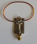
20160725_163519.jpg
The smaller loop is used to lower the inductance, in order to achieve a resonant circuit with the variable capacitor I've soldered in parallel with the loop terminals. In theory, resonance should be present around 2.4 GHz, and the structure should have an impedance of 50 Ohm there. Afterwards, the antenna is connected to a 2.4 Ghz 50/50 Ohm balun.

At the balun input however, I measure an impedance of 20-j20 Ohm. Why does the manufacturer specify both the input and output impedance of the balun? Is it likely that something with the impedance matching of the antenna went wrong (since I cant measure 50 Ohm at the balun input)?

Regards,
Membran
 

Why do you expect it to be 50 ohms?
 

You are right, there is no reason to expect it to be 50 ohms.

1) How would you match the impedance of the loop then before connecting it to the Balun?
2) And what do the Balun specifications of 50 ohms input and output impedance mean? Does it mean that the Balun operates best there and that the impedance is not affected by the Balun itself?
 

Why does the manufacturer specify both the input and output impedance of the balun?

A balun can have various impedance ratios between balanced and unbalanced ports.

Usually the input impedance of a full-wave loop antenna is about 120 ohms, so for a given 50 ohms unbalanced port you need a 2.5 : 1 balun ratio.
But I assume that a normal 2:1 balun should work fine.
 

1. Would be interesting to see a circuit schematic with component values to calculate the matching.
2. Basically yes. I'm not sure however if you manage to connect the balun without parasitic inductance and respective impedance error.

Where (which reference plane) do you see 20 - j20 ohm?
 

@vfone: I've read about the 120 ohms too; initially I planned to use a lambda/4 transformer of 75 ohms to match it to 50 ohms, but since I couldn't manufacture the PCB by myself, I started working with one that was already available.

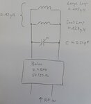
@FvM: This is the corresponding circuit diagram:
20160726_104511.jpg
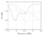
And these are the return losses measured at RF IN (after the Balun):
loopEDA.png
solid: Only the large loop
dashed: Large loop in parallel with the small loop
dotted: Large loop in parallel with the small loop and the variable capacitor (to obtain resonance at around 2.5 GHz)

The 20-j20 ohms impedance was measured at RF IN at 2.5 GHz, using the antenna as depicted, with the small loop and capacitor soldered onto the large loop. I've measured it using the smith chart view on a VNA.

Is this sufficient enough?
 

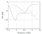
I have uploaded the wrong plots, these are the right ones:
loopEDA.png

solid: Only the large loop
dashed: Large loop in parallel with the small loop
dotted: Large loop in parallel with the small loop and the variable capacitor (to obtain resonance at around 2.5 GHz)

The capacitor however does not lead to the desired resonance, probably because the used capacitance value is still too high.
 
Last edited:

One tunable component won't be enough to get a match, in general. You'll want either a second trimcap, or you'll need to adjust the size of one/both loops.
 

Secondly, if the parallel LC circuit would resonate at 2.4 GHz, it's almost useless, keeping the impedance of the dipole loop as is.

Single turn loop calculation tools give however a quite different inductance for a loop with about 7 mm diameter. Assuming the impedance of a loop with about λ/2 width as inductive is completely wrong.
 

Thank you for your answers.

Secondly, if the parallel LC circuit would resonate at 2.4 GHz, it's almost useless, keeping the impedance of the dipole loop as is.
Could you please elaborate this?


Assuming the impedance of a loop with about λ/2 width as inductive is completely wrong.
Could you elaborate this too?


Is there any reasonable method to tune this antenna if only the large loop of about 105 nH is considered? For resonance at 2.5 GHz, a capacitance value < 1 pF would be required, which is impracticable in my view.
 

Usually the input impedance of a full-wave loop antenna is about 120 ohms

A folded λ/2 dipole has e.g. a real impedance of 290 ohm.

So the full-wave loop antenna with an impedance of typically 120 ohms is now a folded dipole antenna with 290 ohms.
 

You didn't give any circuit dimensions so don't be surprised to get different guesses.

In any case the loop impedance isn't purely inductive.
 

How could a possible design flow look like?

I've designed the large loop (length = lambda) and estimated its inductance; but I can't see a method to determine its capacitive part and hence matching its impedance.
 

Status
Not open for further replies.

Part and Inventory Search

Welcome to EDABoard.com

Sponsor

Back
Top