Continue to Site

Welcome to EDAboard.com

Welcome to our site! EDAboard.com is an international Electronics Discussion Forum focused on EDA software, circuits, schematics, books, theory, papers, asic, pld, 8051, DSP, Network, RF, Analog Design, PCB, Service Manuals... and a whole lot more! To participate you need to register. Registration is free. Click here to register now.

I'm not getting the output pic24fj128ga010

Status
Not open for further replies.

rakshith

Junior Member level 2
Joined
Aug 5, 2012
Messages
23
Helped
0
Reputation
0
Reaction score
0
Trophy points
1,281
Activity points
1,568

Code C - [expand]
1
2
3
4
5
6
7
8
9
10
11
12
13
14
15
16
17
18
19
20
21
22
23
24
25
26
27
28
29
30
31
32
33
34
35
36
37
38
39
40
41
42
43
44
45
46
47
48
49
50
51
52
53
54
55
56
57
58
59
60
61
62
63
64
65
66
67
68
69
70
71
72
73
74
75
76
77
78
79
80
81
82
83
84
85
86
87
88
89
90
91
92
93
94
95
96
97
98
99
100
101
102
103
104
105
106
107
108
109
110
111
112
113
114
115
116
117
118
119
120
121
122
123
124
125
126
127
128
129
130
131
132
133
134
135
136
137
138
139
140
141
142
143
144
145
146
147
148
149
150
151
152
153
154
155
156
157
158
159
160
161
162
163
164
165
166
167
168
169
170
171
172
173
174
175
176
177
178
179
180
181
182
183
184
185
186
187
188
189
190
191
192
193
194
195
196
197
198
199
200
201
202
203
204
205
206
207
208
209
210
211
212
213
214
215
216
217
218
219
220
221
222
223
224
225
226
227
228
229
230
231
232
233
234
235
236
237
238
239
240
241
242
243
244
245
246
247
248
249
250
251
252
253
254
255
256
257
258
259
260
261
262
263
264
265
266
267
268
269
270
271
272
273
274
275
276
277
278
279
280
281
282
283
284
285
286
287
288
289
290
291
292
293
294
295
296
297
298
299
300
301
302
#include <p24FJ128GA010.h>
#include<i2c.h>
#include<uart.h>
 
_CONFIG1(JTAGEN_OFF & GCP_OFF & GWRP_OFF & BKBUG_OFF & ICS_PGx2 & FWDTEN_OFF)
_CONFIG2(IESO_OFF & FCKSM_CSDCMD & OSCIOFNC_ON &  FNOSC_PRI & POSCMOD_HS)
 
 
//#define TIMEOUT 0xff                  // defines the timeout value, must not be too small
#define slave 0x0b
unsigned char isRxReceived;             // this flag will indicate if all characters has been recieved and UART is idle again
unsigned char isLoading;                // this flag will indicate if UART has recieve a single character
unsigned char nBuffOutIdx;              // this index is use to fill buffer, indicator of how many character is loaded on the buffer.. ect
 
char I2CBuffer[16] = "                ";// this is the buffer and limited only to 16 bytes as LCD has 16 characeter per line only
//char dummy;                               // its a dummy variable usually use when disposing the read value
unsigned char bI2CRecieve;              // its a flag used to indicate that I2C is recieving from its master
unsigned char bI2CHasStarted;           // its a flag used to indicate that I2C is done recieving from its master and I2C has detected alredy the stop bit
 
// Globally Defined Methods
void OutToUART();
void I2CInit();
void UARTInit();
unsigned char I2C1Send();
unsigned char I2C1Receive();
unsigned long int TIMEOUT =100;
int main()
{
    UARTInit();              //Initialize UART1 Module
    I2CInit();               //Initialize I2C1 Module
    bI2CRecieve = 0;         //Initialize flags and indeces
    bI2CHasStarted = 0; 
    isRxReceived = 0;
    isLoading = 0;
    nBuffOutIdx = 0;
    
 
    while(1)
    {
    
        
        if( isLoading )
        {                                   // load character receive to output buffer
            char buffer; 
            unsigned long int dly =0;           // initialize delay duration local to this section
    
            while(!U1STAbits.TRMT); 
        
            if( nBuffOutIdx < 16 )          // read RX regbuffer if output buffer is not yet full
            {
                buffer = U1RXREG;   
                I2CBuffer[nBuffOutIdx] = buffer;
                nBuffOutIdx++;
            }
            else
                buffer = U1RXREG;           // discard when out of buffer range
        
            while (dly<205 )                    // delay 205 cycle
            dly++;
 
            if( (U1STAbits.RIDLE))          // is receiver idle?    
            {
                isRxReceived = 1;           // if yes, output buffer to LCD
            }
 
            isLoading = 0;                  // clear is loading flag
 
        }
         
 
        if( isRxReceived )
        {       
        
        unsigned char nIndex = 0;       // reset Global Index
            
            while( nIndex < nBuffOutIdx )   // if index < buffer character count, output character to LCD
            {   
                unsigned short tout = 0;        
            //  U1TXREG = I2CBuffer[nIndex];// send back the character to TX buffer for transmission        
                while ( !U1STAbits.TRMT && tout < TIMEOUT)tout++;   // stay here while character at shift register is not yet transmitted       
                nIndex++;                   // next character
            }   
            
            I2C1Send( );                    // send recived data from buffer to I2C         
            isRxReceived = 0;               // clear receive flag
            nBuffOutIdx = 0;            // reset output buffer index to 0
           // I2C1CONbits.RSEN=1;        //repeated start condition
            //I2C1CONbits.RCEN=1;        // receive enable
        
        }
 
        I2C1Receive();
         
    /*  if( bI2CRecieve )
        {
    
            if( !I2C1STATbits.D_A && !I2C1STATbits.R_W)
            {       
                dummy = I2C1RCV;                // address recieved
                nBuffOutIdx = 0;                // clear buffer index when slave address is recived
                I2C1CONbits.SCLREL = 1;
                bI2CHasStarted = 1; 
                
            }
            if( I2C1STATbits.D_A && !I2C1STATbits.R_W)
            {
            
                I2CBuffer[nBuffOutIdx] = I2C1RCV & 0xff;    // data recieved then stored to buffer
                I2C1CONbits.SCLREL = 1;         // release the clock
                nBuffOutIdx++;                  // increment buffer index
 
 
            }
 
            bI2CRecieve = 0;                    // clear the section flag
        }
 
        if( bI2CHasStarted && I2C1STATbits.P )
        {
 
             bI2CHasStarted = 0;                // clear the section flag
             OutToUART();                       // send to hyperterminal by UART TX
             
        }
    
 
    }
 
return 0;*/
}
 
void OutToUART()
{
 
    unsigned char i = 0;
    
 
    while( i < nBuffOutIdx )
    {   unsigned tout = 0;
        U1TXREG = I2CBuffer[i];// send back the character to TX buffer for transmission     
        while ( !U1STAbits.TRMT && tout < TIMEOUT)tout++;   // stay here while character at shift register is not yet transmitted       
        i++;
    }


}
 
    unsigned char I2C1Send( )
      {
            unsigned char len = 0;
            unsigned char to = 0;
            I2C1CONbits.SEN = 1;        // Set start bit        
            
            while( I2C1STATbits.S && (to < TIMEOUT) )to++;  // wait for start bit flag to set
            to = 0;
 
            I2C1TRN = (slave << 1) & 0xFE;              // send (slave + write bit )        
 
            while ( I2C1STATbits.TRSTAT && (to < TIMEOUT))to++; // wait for Transmit bit to be cleared
            to = 0;
            if( I2C1STATbits.ACKSTAT )
            {
        //  I2C1CONbits.PEN = 1;        // Set stop bit
            return 1;                   // ret 1 if NAK
            }
 
            while ( len < nBuffOutIdx )
            {
 
                I2C1TRN = I2CBuffer[len];               // send data
                
                while ( I2C1STATbits.TRSTAT && (to < TIMEOUT) )to++;    // wait for Transmit bit to be cleared
                to = 0;
                len++;
 
                if( I2C1STATbits.ACKSTAT )
                {
                I2C1CONbits.PEN = 1;        // Set stop bit
                return 1;                   // ret 1 if NAK
                I2C1CONbits.SCLREL = 1;
                }
 
            }   
            
        I2C1CONbits.PEN = 1;        // Set stop bit     
        
            return 0;
 
    }
unsigned char I2C1Receive();
{
   
    I2C1CONbits.RSEN=1;        //repeated start condition
    I2C1TRN = (slave << 1) & 0xFF;              // send (slave + write bit )    
    if( I2C1STATbits.ACKSTAT )
    {
      I2C1CONbits.RCEN=1;        // receive enable
    }
    if(I2C1STATbits.RBF)
    {
      I2C1CONbits.PEN = 1;      // Set stop bit
       return 1;
    }
    I2CBuffer[nBuffOutIdx] = I2C1RCV & 0xff;    // data recieved then stored to buffer
   //   I2C1CONbits.SCLREL = 1;         // release the clock
    nBuffOutIdx++;                  // increment buffer index
}
 
OutToUART();
 
 
void __attribute__((interrupt, shadow, no_auto_psv)) _SI2C1Interrupt()
{
 
    bI2CRecieve = 1;
    IFS1bits.SI2C1IF = 0;                   // manually cleared SI2C1 Interrupt flag
 
}
 
 
void I2CInit()
{
 
    //I2C1MSK = 0x00;           // set this controller's device address
 
    I2C1CONbits.I2CEN = 1;      // enable I2C module
    I2C1CONbits.I2CSIDL = 0;    // Continue module operation in Idle mode
    //I2C1CONbits.SCLREL = ; 
    I2C1CONbits.IPMIEN = 0;     // IPMI mode disabled
    I2C1CONbits.A10M = 0;       // I2C1ADD is a 7-bit slave address
    I2C1CONbits.DISSLW = 0;     // for 400 kHz up enable slew rate
    I2C1CONbits.SMEN = 1;       // signal conditioning
    I2C1CONbits.GCEN = 0;       // for slave mode only
    I2C1CONbits.STREN = 1;      // Enable software or receive clock stretching, therefore clock must be release by slave when done on loading data to sync clock
 
    I2C1BRG = 31;               // use 1MHz SCL frequency but apparently, its frequency is 666 kHz
 
    IEC1bits.SI2C1IE = 1;       // enable Slave I2C1 interrupt
    IEC1bits.MI2C1IE = 1;       // enable Master I2C1 interrupt
 
}
 
void UARTInit()
{
    
    U1BRG = 25;                 // 9600 
 
    U1MODEbits.UARTEN = 1;      // UART1 is Enabled
    U1MODEbits.USIDL = 0;       // Continue operation at Idlestate
    U1MODEbits.IREN = 0;        // IrDA En/Decoder is disabled
    U1MODEbits.RTSMD = 0;       // flow control mode
    //U1MODEbits.UEN = 0b10;        // UTX, RTX, U1CTS, U1RTS are enable and on use.
    U1MODEbits.WAKE = 1;        // Wake-up on start bit is enabled
    U1MODEbits.LPBACK = 0;      // Loop-back is disabled
    U1MODEbits.ABAUD = 0;       // auto baud is disabled
    U1MODEbits.RXINV = 0;       // No RX inversion
    U1MODEbits.BRGH = 0;        // low boud rate
    U1MODEbits.PDSEL = 0b00;    // 8bit no parity
    U1MODEbits.STSEL = 0;       // one stop bit 
        
 
    U1STAbits.UTXISEL1 = 0b00;  
    //U1STAbits.TXINV = 0;      // cant compile TXINV.. why???
    U1STA &= 0xDFFF;            // clear TXINV by bit masking
    U1STAbits.UTXBRK = 0;       // sync break tx is disabled
    U1STAbits.UTXEN = 1;        //transmit  is enabled
    U1STAbits.URXISEL = 0b00;   // interrupt flag bit is set when RXBUF is filled whith 1 character
    U1STAbits.ADDEN = 0;        // address detect mode is disabled
 
    IFS0bits.U1RXIF = 0;        // clear interrupt flag of rx
    IEC0bits.U1RXIE = 1;        // enable rx recieved data interrupt
 
    IFS0bits.U1TXIF = 0;        // clear interrupt flag of rx
    IEC0bits.U1TXIE = 1;        // enable rx recieved data interrupt
 
 
}
 
void __attribute__((interrupt, shadow, no_auto_psv)) _U1RXInterrupt()
{
 
    IFS0bits.U1RXIF = 0;                    // manually cleared U1RX Interrupt flag
    isLoading = 1;                          // signal main to store character recieve to buffer
 
}
 
void __attribute__((interrupt, shadow, no_auto_psv)) _U1TXInterrupt()
{
 
    IFS0bits.U1TXIF = 0;                    // manually cleared U1RX Interrupt flag
 
}
 
 
void __attribute__((interrupt, shadow, no_auto_psv)) _MI2C1Interrupt()
{
 
    IFS1bits.MI2C1IF = 0;                   // manually cleared MI2C1 Interrupt flag
 
}
}


Attachments

  • New Text Document.txt
    8.5 KB · Views: 146
Last edited by a moderator:

for a start you have missmatched {} in main(), e.g. line 127 to 130
Code:
    }
 
return 0;*/
}
should be
Code:
*/    }
 
return 0;
}
also you have a ; on the end of line 191 which should not be there
Code:
unsigned char I2C1Receive();
 

Horace 1 :


I made these changes , in spite i'm not getting the output..!
 

Can you zip and upload the proteus .dsn file?

In your code

Code:
int main()
{
    UARTInit();              //Initialize UART1 Module
    I2CInit();               //Initialize I2C1 Module
    bI2CRecieve = 0;         //Initialize flags and indeces
    bI2CHasStarted = 0; 
    isRxReceived = 0;
    isLoading = 0;
    nBuffOutIdx = 0;
    
 
    while(1)
    {
    
        
        if( isLoading )
        {

Code:
 isLoading = 0;
then how can
Code:
  if( isLoading )
work?

Same with
Code:
 isRxReceived = 0;
Code:
 if( isRxReceived )
 
Last edited:

what is line 210 for? remove it?

you appear to have a spare } at the end of the code


Code C - [expand]
1
2
3
4
5
6
7
8
9
10
11
12
13
14
15
16
17
18
19
20
21
22
23
24
25
26
27
28
29
30
31
32
33
34
35
36
37
38
39
40
41
42
43
44
45
46
47
48
49
50
51
52
53
54
55
56
57
58
59
60
61
62
63
64
65
66
67
68
69
70
71
72
73
74
75
76
77
78
79
80
81
82
83
84
85
86
87
88
89
90
91
92
93
94
95
96
97
98
99
100
101
102
103
104
105
106
107
108
109
110
111
112
113
114
115
116
117
118
119
120
121
122
123
124
125
126
127
128
129
130
131
132
133
134
135
136
137
138
139
140
141
142
143
144
145
146
147
148
149
150
151
152
153
154
155
156
157
158
159
160
161
162
163
164
165
166
167
168
169
170
171
172
173
174
175
176
177
178
179
180
181
182
183
184
185
186
187
188
189
190
191
192
193
194
195
196
197
198
199
200
201
202
203
204
205
206
207
208
209
210
211
212
213
214
215
216
217
218
219
220
221
222
223
224
225
226
227
228
229
230
231
232
233
234
235
236
237
238
239
240
241
242
243
244
245
246
247
248
249
250
251
252
253
254
255
256
257
#include <p24FJ128GA010.h>
 
_CONFIG1(JTAGEN_OFF & GCP_OFF & GWRP_OFF & BKBUG_OFF & ICS_PGx2 & FWDTEN_OFF)
_CONFIG2(IESO_OFF & FCKSM_CSDCMD & OSCIOFNC_ON &  FNOSC_PRI & POSCMOD_HS)
 
 
//#define TIMEOUT 0xff                  // defines the timeout value, must not be too small
#define slave 0x0b
unsigned char isRxReceived;             // this flag will indicate if all characters has been recieved and UART is idle again
unsigned char isLoading;                // this flag will indicate if UART has recieve a single character
unsigned char nBuffOutIdx;              // this index is use to fill buffer, indicator of how many character is loaded on the buffer.. ect
 
 char I2CBuffer[16] = "                ";// this is the buffer and limited only to 16 bytes as LCD has 16 characeter per line only
//char dummy;                               // its a dummy variable usually use when disposing the read value
unsigned char bI2CRecieve;              // its a flag used to indicate that I2C is recieving from its master
unsigned char bI2CHasStarted;           // its a flag used to indicate that I2C is done recieving from its master and I2C has detected alredy the stop bit
 
// Globally Defined Methods
void OutToUART();
void I2CInit();
void UARTInit();
unsigned char I2C1Send();
unsigned char I2C1Receive();
unsigned long int TIMEOUT =100;
 
void __attribute__((interrupt, shadow, no_auto_psv)) _U1RXInterrupt()
{
 
    IFS0bits.U1RXIF = 0;                    // manually cleared U1RX Interrupt flag
    isLoading = 1;                          // signal main to store character recieve to buffer
 
}
 
void __attribute__((interrupt, shadow, no_auto_psv)) _U1TXInterrupt()
{
 
    IFS0bits.U1TXIF = 0;                    // manually cleared U1RX Interrupt flag
 
}
 
 
void __attribute__((interrupt, shadow, no_auto_psv)) _MI2C1Interrupt()
{
 
    IFS1bits.MI2C1IF = 0;                   // manually cleared MI2C1 Interrupt flag
 
}


int main()
{
    UARTInit();              //Initialize UART1 Module
    I2CInit();               //Initialize I2C1 Module
    bI2CRecieve = 0;         //Initialize flags and indeces
    bI2CHasStarted = 0; 
    isRxReceived = 0;
    isLoading = 0;
    nBuffOutIdx = 0;
    
 
    while(1)
    {
    
        
        if( isLoading )
        {                                   // load character receive to output buffer
            char buffer; 
            unsigned long int dly =0;           // initialize delay duration local to this section
    
            while(!U1STAbits.TRMT); 
        
            if( nBuffOutIdx < 16 )          // read RX regbuffer if output buffer is not yet full
            {
                buffer = U1RXREG;   
                I2CBuffer[nBuffOutIdx] = buffer;
                nBuffOutIdx++;
            }
            else
                buffer = U1RXREG;           // discard when out of buffer range
        
            while (dly<205 )                    // delay 205 cycle
            dly++;
 
            if( (U1STAbits.RIDLE))          // is receiver idle?    
            {
                isRxReceived = 1;           // if yes, output buffer to LCD
            }
 
            isLoading = 0;                  // clear is loading flag
 
        }
         
        I2C1Send( );// send recived data from buffer to I2C     
    I2C1Receive();
        if( isRxReceived )
        {       


           isRxReceived = 0;                // clear receive flag
            nBuffOutIdx = 0;            // reset output buffer index to 0
            OutToUART( );
        }


}
         
         
return(0);         
 
}
         
 
    unsigned char I2C1Send( )
      {
            unsigned char len = 0;
            unsigned char to = 0;
            I2C1CONbits.SEN = 1;        // Set start bit        
            
            while( I2C1STATbits.S && (to < TIMEOUT) )to++;  // wait for start bit flag to set
            to = 0;
 
            I2C1TRN = (slave << 1) & 0xFE;              // send (slave + write bit )        
 
            while ( I2C1STATbits.TRSTAT && (to < TIMEOUT))to++; // wait for Transmit bit to be cleared
            to = 0;
            if( !I2C1STATbits.ACKSTAT )
            {
            I2C1CONbits.PEN = 1;        // Set stop bit
            return 1;                   // ret 1 if NAK
            }
 
            while ( len < nBuffOutIdx )
            {
 
                I2C1TRN = I2CBuffer[len];               // send data
                
                while ( I2C1STATbits.TRSTAT && (to < TIMEOUT) )to++;    // wait for Transmit bit to be cleared
                to = 0;
                len++;
 
                if( I2C1STATbits.ACKSTAT )
                {
                I2C1CONbits.PEN = 1;        // Set stop bit
                return 1;                   // ret 1 if NAK
                I2C1CONbits.SCLREL = 1;
                }
 
            }   
            
        //I2C1CONbits.PEN = 1;      // Set stop bit     
        
            return 0;
 
    }
unsigned char I2C1Receive()
{
   
    I2C1CONbits.RSEN=1;        //repeated start condition
    I2C1TRN = (slave << 1) & 0xFF;              // send (slave + write bit )    
    if( I2C1STATbits.ACKSTAT )
    {
      I2C1CONbits.PEN = 1;  
      I2C1CONbits.RCEN=1;        // receive enable
    }
    if(I2C1STATbits.RBF)
    I2C1CONbits.PEN = 1;        // Set stop bit
    I2CBuffer[nBuffOutIdx] = I2C1RCV & 0xFF;    // data recieved then stored to buffer
    I2C1CONbits.SCLREL = 1;         // release the clock
    nBuffOutIdx++;                  // increment buffer index
}
void OutToUART( )
{
 
    unsigned char i = 0;
    
 
    while( i < nBuffOutIdx )
    {   unsigned tout = 0;
        U1TXREG = I2CBuffer[i];// send back the character to TX buffer for transmission     
        while ( !U1STAbits.TRMT && tout < TIMEOUT)tout++;   // stay here while character at shift register is not yet transmitted       
        i++;
    }


}


void __attribute__((interrupt, shadow, no_auto_psv)) _SI2C1Interrupt()
{
 
    bI2CRecieve = 1;
    IFS1bits.SI2C1IF = 0;                   // manually cleared SI2C1 Interrupt flag
 
}
 
 
void I2CInit( )
{
 
    //I2C1MSK = 0x00;           // set this controller's device address
 
    I2C1CONbits.I2CEN = 1;      // enable I2C module
    I2C1CONbits.I2CSIDL = 0;    // Continue module operation in Idle mode
    I2C1CONbits.SCLREL =1 ; 
    I2C1CONbits.IPMIEN = 0;     // IPMI mode disabled
    I2C1CONbits.A10M = 0;       // I2C1ADD is a 7-bit slave address
    I2C1CONbits.DISSLW = 0;     // for 400 kHz up enable slew rate
    I2C1CONbits.SMEN = 1;       // signal conditioning
    I2C1CONbits.GCEN = 0;       // for slave mode only
    I2C1CONbits.STREN = 1;      // Enable software or receive clock stretching, therefore clock must be release by slave when done on loading data to sync clock
 
    I2C1BRG = 31;               // use 1MHz SCL frequency but apparently, its frequency is 666 kHz
 
    IEC1bits.SI2C1IE = 1;       // enable Slave I2C1 interrupt
    IEC1bits.MI2C1IE = 1;       // enable Master I2C1 interrupt
 
}
 
void UARTInit( )
{
    
    U1BRG =25;                  // 9600 
 
    U1MODEbits.UARTEN = 1;      // UART1 is Enabled
    U1MODEbits.USIDL = 0;       // Continue operation at Idlestate
    U1MODEbits.IREN = 0;        // IrDA En/Decoder is disabled
    U1MODEbits.RTSMD = 0;       // flow control mode
    //U1MODEbits.UEN = 0b10;        // UTX, RTX, U1CTS, U1RTS are enable and on use.
    U1MODEbits.WAKE = 1;        // Wake-up on start bit is enabled
    U1MODEbits.LPBACK = 0;      // Loop-back is disabled
    U1MODEbits.ABAUD = 0;       // auto baud is disabled
    U1MODEbits.RXINV = 0;       // No RX inversion
    U1MODEbits.BRGH = 0;        // low boud rate
    U1MODEbits.PDSEL = 0b00;    // 8bit no parity
    U1MODEbits.STSEL = 0;       // one stop bit 
        
 
    U1STAbits.UTXISEL1 = 0b00;  
    //U1STAbits.TXINV = 0;      // cant compile TXINV..why??
    U1STA &= 0xDFFF;            // clear TXINV by bit masking
    U1STAbits.UTXBRK = 0;       // sync break tx is disabled
    U1STAbits.UTXEN = 1;        //transmit  is enabled
    //U1STAbits.URXISEL = 0b00; // interrupt flag bit is set when RXBUF is filled whith 1 character
    U1STAbits.ADDEN = 0;        // address detect mode is disabled
 
    IFS0bits.U1RXIF = 0;        // clear interrupt flag of rx
    IEC0bits.U1RXIE = 1;        // enable rx recieved data interrupt


}


- - - Updated - - -

horace 1 :

I'v made few changes including things u said...!

I'm not able to get any output..!

- - - Updated - - -

internetuser2k12 :

This is the file which i'm using..!

I'v deleted LCD part in this..! n only uart n i2c r configured..
 

Attachments

  • CE363 - Hyperterminal - UART - I2C - LCD.zip
    22.8 KB · Views: 88
Last edited by a moderator:

Which Compiler are you using? Can you upload the Schematic? Where are the TRIS Commands?
 
Last edited:

internetuser2k12 :

I'm using c30 compiler in MPLAB IDE v8.60.
I using docklight to send n receive commands.
 

Can you upload the schematic, so that it can be simulated in proteus?
 

internetuser2k12 :

Actually i do't require TRIS commands for this program know??

I really do't know what s meant by SCHEMATIC" - whats that???
 

I don't know exactly. But can you try TRIS. Schematic = Circuit diagram.
 

internetuser2k12 :

As i know TRIS s for input n output ports ,i'm using UART n I@C.!
anyways i'l hv a try eve on that.

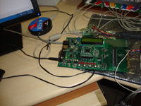
I'm usings PIC24FJ128GA010 mounted on Explrer 16 board,n i've made connection thru soldering UART n I2C found by data specification sheet of pic24fj128ga010.

do u want a photo of the things which i'm or the data sheet's of all this which contains schematic .


internetuser2k12 :

r these fine..?
 

No. It doesn't work. I want to know to which ports your lcd and other things are connected. Can you draw the schematic in proteus? OK I got the Explorer 16 in proteus. Can you send the full source code which compiles so that I can debug in proteus and see?

Have you cannected pull up resistors to the SCL and SDA lines as mentioned here http://www.robot-electronics.co.uk/acatalog/I2C_Tutorial.html
 
Last edited:

internetuser2k12 :

As i know TRIS s for input n output ports ,i'm using UART n I@C.!
anyways i'l hv a try eve on that.

I'm usings PIC24FJ128GA010 mounted on Explrer 16 board,n i've made connection thru soldering UART n I2C found by data specification sheet of pic24fj128ga010.

do u want a photo of the things which i'm or the data sheet's of all this which contains schematic .
any reason why you are using UART1 rather than UART2 which is connected to P1 the 9 pin D type connector of the explorer 16 (next to the power connector)?
this code prints "hello world" to UART2 at 9600 baud correctly (I have changed UART1 code to UART2 and added two functions)
Code:
#include <p24FJ128GA010.h>

_CONFIG1(JTAGEN_OFF & GCP_OFF & GWRP_OFF & BKBUG_OFF & ICS_PGx2 & FWDTEN_OFF)
_CONFIG2(IESO_OFF & FCKSM_CSDCMD & OSCIOFNC_ON &  FNOSC_PRI & POSCMOD_HS)


//#define TIMEOUT 0xff					// defines the timeout value, must not be too small
#define slave 0x0b
unsigned char isRxReceived;				// this flag will indicate if all characters has been recieved and UART is idle again
unsigned char isLoading;				// this flag will indicate if UART has recieve a single character
unsigned char nBuffOutIdx;				// this index is use to fill buffer, indicator of how many character is loaded on the buffer.. ect

 char I2CBuffer[16] = "                ";// this is the buffer and limited only to 16 bytes as LCD has 16 characeter per line only
//char dummy;								// its a dummy variable usually use when disposing the read value
unsigned char bI2CRecieve;				// its a flag used to indicate that I2C is recieving from its master
unsigned char bI2CHasStarted;			// its a flag used to indicate that I2C is done recieving from its master and I2C has detected alredy the stop bit

// Globally Defined Methods
void OutToUART();
void I2CInit();
void UARTInit();
unsigned char I2C1Send();
unsigned char I2C1Receive();
unsigned long int TIMEOUT =100;

void __attribute__((interrupt, shadow, no_auto_psv)) _U2RXInterrupt()
{

	IFS1bits.U2RXIF = 0;					// manually cleared U2RX Interrupt flag
	isLoading = 1;							// signal main to store character recieve to buffer

}

void __attribute__((interrupt, shadow, no_auto_psv)) _U2TXInterrupt()
{

	IFS1bits.U2TXIF = 0;					// manually cleared U2RX Interrupt flag

}


void __attribute__((interrupt, shadow, no_auto_psv)) _MI2C1Interrupt()
{

	IFS1bits.MI2C1IF = 0;					// manually cleared MI2C1 Interrupt flag

}


int main()
{
	UARTInit();              //Initialize UART1 Module
	UART2PrintString("hello world\r\n");
	I2CInit();				 //Initialize I2C1 Module
	bI2CRecieve = 0;		 //Initialize flags and indeces
	bI2CHasStarted = 0;	
	isRxReceived = 0;
	isLoading = 0;
	nBuffOutIdx = 0;
	

	while(1)
	{
	
		
		if( isLoading )
		{									// load character receive to output buffer
			char buffer; 
			unsigned long int dly =0;			// initialize delay duration local to this section
	
			while(!U2STAbits.TRMT);	
		
			if( nBuffOutIdx < 16 )			// read RX regbuffer if output buffer is not yet full
			{
				buffer = U2RXREG;	
				I2CBuffer[nBuffOutIdx] = buffer;
				nBuffOutIdx++;
			}
			else
				buffer = U2RXREG;			// discard when out of buffer range
		
			while (dly<205 )					// delay 205 cycle
			dly++;

			if( (U2STAbits.RIDLE))			// is receiver idle?	
			{
				isRxReceived = 1;			// if yes, output buffer to LCD
			}

			isLoading = 0;					// clear is loading flag

		}
         
        I2C1Send( );// send recived data from buffer to I2C		
	I2C1Receive();
		if( isRxReceived )
		{		


		   isRxReceived = 0;				// clear receive flag
			nBuffOutIdx = 0;			// reset output buffer index to 0
            OutToUART( );
		}


}
         
         
return(0);         

}
         

	unsigned char I2C1Send( )
      {
			unsigned char len = 0;
			unsigned char to = 0;
			I2C1CONbits.SEN = 1;		// Set start bit		
			
			while( I2C1STATbits.S && (to < TIMEOUT) )to++;	// wait for start bit flag to set
			to = 0;

			I2C1TRN = (slave << 1) & 0xFE;				// send (slave + write bit )		

			while ( I2C1STATbits.TRSTAT && (to < TIMEOUT))to++;	// wait for Transmit bit to be cleared
			to = 0;
			if( !I2C1STATbits.ACKSTAT )
			{
			I2C1CONbits.PEN = 1;		// Set stop bit
			return 1;					// ret 1 if NAK
			}

			while ( len < nBuffOutIdx )
			{

				I2C1TRN = I2CBuffer[len];				// send data
				
				while ( I2C1STATbits.TRSTAT && (to < TIMEOUT) )to++;	// wait for Transmit bit to be cleared
				to = 0;
				len++;

				if( I2C1STATbits.ACKSTAT )
				{
				I2C1CONbits.PEN = 1;		// Set stop bit
				return 1;					// ret 1 if NAK
			    I2C1CONbits.SCLREL = 1;
				}

			}	
			
		//I2C1CONbits.PEN = 1;		// Set stop bit		
		
			return 0;

    }
unsigned char I2C1Receive()
{
   
    I2C1CONbits.RSEN=1;        //repeated start condition
	I2C1TRN = (slave << 1) & 0xFF;				// send (slave + write bit )	
    if( I2C1STATbits.ACKSTAT )
	{
	  I2C1CONbits.PEN = 1;	
      I2C1CONbits.RCEN=1;        // receive enable
    }
    if(I2C1STATbits.RBF)
    I2C1CONbits.PEN = 1;		// Set stop bit
    I2CBuffer[nBuffOutIdx] = I2C1RCV & 0xFF;	// data recieved then stored to buffer
   	I2C1CONbits.SCLREL = 1;			// release the clock
	nBuffOutIdx++;					// increment buffer index
}
void OutToUART( )
{

	unsigned char i = 0;
	

	while( i < nBuffOutIdx )
	{	unsigned tout = 0;
		U2TXREG = I2CBuffer[i];// send back the character to TX buffer for transmission		
		while ( !U2STAbits.TRMT && tout < TIMEOUT)tout++;	// stay here while character at shift register is not yet transmitted		
		i++;
	}


}


void __attribute__((interrupt, shadow, no_auto_psv)) _SI2C1Interrupt()
{

	bI2CRecieve = 1;
	IFS1bits.SI2C1IF = 0;					// manually cleared SI2C1 Interrupt flag

}


void I2CInit( )
{

	//I2C1MSK = 0x00; 			// set this controller's device address

	I2C1CONbits.I2CEN = 1;		// enable I2C module
	I2C1CONbits.I2CSIDL = 0;	// Continue module operation in Idle mode
	I2C1CONbits.SCLREL =1 ; 
	I2C1CONbits.IPMIEN = 0;		// IPMI mode disabled
	I2C1CONbits.A10M = 0;		// I2C1ADD is a 7-bit slave address
	I2C1CONbits.DISSLW = 0; 	// for 400 kHz up enable slew rate
	I2C1CONbits.SMEN = 1; 		// signal conditioning
	I2C1CONbits.GCEN = 0;  		// for slave mode only
	I2C1CONbits.STREN = 1;  	// Enable software or receive clock stretching, therefore clock must be release by slave when done on loading data to sync clock

	I2C1BRG = 31;				// use 1MHz SCL frequency but apparently, its frequency is 666 kHz

	IEC1bits.SI2C1IE = 1;		// enable Slave I2C1 interrupt
	IEC1bits.MI2C1IE = 1;		// enable Master I2C1 interrupt

}

void UARTInit( )
{
	
	U2BRG =25;					// 9600 

	U2MODEbits.UARTEN = 1;		// UART1 is Enabled
	U2MODEbits.USIDL = 0;		// Continue operation at Idlestate
	U2MODEbits.IREN = 0;		// IrDA En/Decoder is disabled
	U2MODEbits.RTSMD = 0; 		// flow control mode
	//U2MODEbits.UEN = 0b10;		// UTX, RTX, U2CTS, U2RTS are enable and on use.
	U2MODEbits.WAKE = 1;		// Wake-up on start bit is enabled
	U2MODEbits.LPBACK = 0;		// Loop-back is disabled
	U2MODEbits.ABAUD = 0;		// auto baud is disabled
	U2MODEbits.RXINV = 0;		// No RX inversion
	U2MODEbits.BRGH = 0;		// low boud rate
	U2MODEbits.PDSEL = 0b00; 	// 8bit no parity
	U2MODEbits.STSEL = 0;		// one stop bit	
		

	U2STAbits.UTXISEL1 = 0b00;	
	//U2STAbits.TXINV = 0; 		// cant compile TXINV..why??
	U2STA &= 0xDFFF;			// clear TXINV by bit masking
	U2STAbits.UTXBRK = 0;		// sync break tx is disabled
	U2STAbits.UTXEN = 1;		//transmit  is enabled
	//U2STAbits.URXISEL = 0b00;	// interrupt flag bit is set when RXBUF is filled whith 1 character
	U2STAbits.ADDEN = 0;		// address detect mode is disabled

	IFS1bits.U2RXIF = 0;		// clear interrupt flag of rx
	IEC1bits.U2RXIE = 1;		// enable rx recieved data interrupt


}

// Function:UART PutChar - This routine writes a character to the transmit FIFO
void UART2PutChar(const char ch )
{
    while(U2STAbits.TRMT == 0);	// wait for transmit ready
    U2TXREG = ch;				// transmit character
}

//Function:UART PrintString - prints a string of characters to the UART.
void UART2PrintString(const char *str )
{
    char c;
    while( (c = *str++) )
       UART2PutChar(c);
}
now you know that UART2 works you can try UART1 and then the I2C
 

internetuser2k12 :

I'v given u a zip file above kno. that include everything..
The source file supporting file everything..

- - - Updated - - -

horace 1 :

i'm not able to use UART2 cuz, that pin is not working properly here..
even i did this this for UART2,i was failed . so i changed all the UART2 to UART1 the it worked..
So,i'm not using UART2. But UART1 s fine ..

- - - Updated - - -

internetuser2k12 :

yes, i'v .. connected pull up registers as u said..!

but still i'm in d same stage.
 

The code Compiled and I am getting the output shown in image.

In the code
Code:
 U2MODEbits.UARTEN = 1;		// UART1 is Enabled
UART1 is defined but you are using UART2. Isn't it? Can you change the code according to UART2? Or is it UART2 enabled?
 

Attachments

  • ss25.jpg
    ss25.jpg
    167.2 KB · Views: 118
Last edited:

horace 1:

i got the output as u said whn i changed the UART2 to UART1..
So, UART2 in our board is't working..!

I'm good with UART1..

What to do next..!.?

- - - Updated - - -

i do't understand anything..!:(
 

Status
Not open for further replies.

Similar threads

Part and Inventory Search

Welcome to EDABoard.com

Sponsor

Back
Top