Continue to Site

Welcome to EDAboard.com

Welcome to our site! EDAboard.com is an international Electronics Discussion Forum focused on EDA software, circuits, schematics, books, theory, papers, asic, pld, 8051, DSP, Network, RF, Analog Design, PCB, Service Manuals... and a whole lot more! To participate you need to register. Registration is free. Click here to register now.

I'm new for proteus isis

Status
Not open for further replies.

mamush2013

Newbie level 4
Newbie level 4
Joined
Mar 10, 2013
Messages
6
Helped
0
Reputation
0
Reaction score
0
Trophy points
1,281
Visit site
Activity points
1,339
Hello there
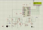
i'm working on my FYP! i face a difficulty when i was working the simulation part of my work! The component placement and connection looks like as indicated on the figure. as the error message indicates, in my opinion the cause of the error is the opamp LM324! i need your hand if u experienced and solve this type of problem before!
 

post your schematic and error sentence , i am an experienced user and i have done tons of simulations on ISIS and i can help you .
 
Until n unless you post your schematic nobody could help you out here!!
 

thank you!! sorry for my lateness!! i rectify the problem! but i'm here with another problem!!
I need Assistance on embedded programing!?
i'm final year biomedical engineering student! i'm working my FYP!! my work is to design a multi- parameter human vital sign measuring device. the parameters are blood pressure,heart rate and body temperature! the project is embedded project. i use sensors micro-controller(pic18f452) and a display unit(LCD) to my design. i face a difficulty while writing the c program!! i can't convert the value i get from the heart rate sensor to a heart rate!! i need the calculation or code that converts the voltage from the sensor to the readable heart rate value!!
let's make things clear i'm using the following materials for my design
1. proteus isis simulation software
2. mplab x current version for my c codding
3 c18 c compiler
here is my code!
Code:
/*
 * File:   Temprature.c
 * Author: TOSHIBA
 *
 * Created on May 5, 2013, 3:54 AM
 */

#include <stdio.h>
#include <stdlib.h>
#include <adc.h>
#include<delays.h>
#include<string.h>
#include<p18f452.h>
#pragma config WDT=OFF,OSC=HS,OSCS=OFF,BORV=45,PWRT=ON,BOR=ON


#define rs PORTCbits.RC5
#define rw PORTCbits.RC6
#define en PORTCbits.RC7
#define sdata PORTD


void lcdcmd(unsigned char);
void lcddata(unsigned char);
void adc_con(int);
void adc_con1(int);
void adc_init(void);
void Print_string(char *A);
void Delay_ms(int);

char HR[]="Heart Rate";
char NO[]="PRESS BUTTON";
float LDR[10],avg_output=0,temp;
unsigned int i=0;
/*
 *
 *
 */
void main(void)
{
    TRISA=0x0f;        // Configure RA3 as input pin
    TRISB=0;        // Configure Port B as output port
    TRISC=0;
    TRISD=0;
            // Set cursor position to 1st line, 1st column


     TRISBbits.RB4=1;
     TRISBbits.RB5=1;
     TRISBbits.RB6=1;

    adc_init();        //ADC Initialization

    while(PORTBbits.RB5==1)
    {
            lcdcmd(0x38);        // Configure the LCD in 8-bit mode, 2 line and 5x7 font
            lcdcmd(0x0C);        // Display On and Cursor Off
            lcdcmd(0x01);        // Clear display screen
            lcdcmd(0x06);        // Increment cursor
            lcdcmd(0x80);
            Print_string(HR);
            lcdcmd(0x87);
            ADCON0=0xD1;
            ADRES=0;
            temp=0;
            for(i=0;i<10;i++)
                {
                    ADCON0bits.GO=1;                     // Start A/D
                    while(ADCON0bits.DONE==1);             // Wait

                    LDR[i]=ADRES ;                     //Store data
                    Delay_ms(5);
                    temp=temp+LDR[i];

                }
                avg_output=temp/10;
                avg_output=(1024-avg_output);                  // Take average
                adc_con(avg_output);

    }
    while(PORTBbits.RB5==0){
        lcdcmd(0x38);        // Configure the LCD in 8-bit mode, 2 line and 5x7 font
        lcdcmd(0x0C);        // Display On and Cursor Off
        lcdcmd(0x01);        // Clear display screen
        lcdcmd(0x06);        // Increment cursor
        lcdcmd(0x80);
        Print_string(NO);
        lcdcmd(0x87);
        Delay_ms(1000);
    }
}
void lcdcmd(unsigned char cmdout)
{
    sdata=cmdout;        //Send command to lcdport=PORTB
    rs=0;
    rw=0;
    en=1;
    Delay_ms(20);
    en=0;
}

void Delay_ms(int d)
{
    int i,j;
    for(i=0;i<d;i++)
    {
        for(j=0;j<d;j++)
        {
        }
    }
}
void adc_init()
{
    ADCON1=0xC0;                   // Make RA0/AN0 ,RA1,RA2,RA3,RA4,RA5,RA6 and RA7 ANALOG
                                // Select Channel0 & ADC off
                                   //     ADCON2=0x85;                            //  Fosc/32 clock option
    ADCON0=0xD1;                          // AN3... clock drived from internal RC Enable ADC
}
void adc_con( int adc_out)
{
    int adc_out1;
    int i=0;
    char position=0xC3;
    for(i=0;i<=3;i++)
    {
        adc_out1=adc_out%10;                     // To exract the unit position digit
        adc_out=adc_out/10;
        lcdcmd(position);
        lcddata(48+adc_out1);                    // Convert into its corresponding ASCII
        position--;

    }
    Delay_ms(100);
}
void adc_con1( int adc)
{
    int adc_out2;
    int i=0;
    char position=0xCF;
    for(i=0;i<=3;i++)
    {
        adc_out2=adc%10;                     // To exract the unit position digit
        adc=adc/10;
        lcdcmd(position);
        lcddata(48+adc_out2);                    // Convert into its corresponding ASCII
        position--;

    }
}
void lcddata(unsigned char dataout)
{

    sdata=dataout;    //Send data to lcdport=PORTB
    rs=1;
    rw=0;
    en=1;
    Delay_ms(30);
    en=0;
}
void Print_string(char *a)
{
 int i;
 for(i=0;(*(a+i))!='\0';i++)
   {
     lcddata(*(a+i));
   }
}
 

No need for the code, its with the sensor specification : you say i that you want to transform the voltage read by the ADC of microcontroller to a heart beat value !

the equation should be available in the datasheet of your sensor in a table or curve !? give me the name of the sensor or the upload the datasheet and i can help you with that if you want
 
thank you for your kindness
the sensor i use is Light dependent resistor(LDR)!! if you see in the code the analog digital conversion is already done!! but the output is not the heart rate!! it's the lights intensity on the LDR!! use any LDR datasheet and tell me clue or code how it works on proteus isis simulator!! it's better if i upload the circuit of my design but i face a challenge to upload it!! lets make an image what ma design look like!! there is a light source(LED) that shines it's light on the finger tip. the light pass/ reflected from the finger illuminated on the LDR! the LDR's resistance varies depending on the intensity of the light reached to it. due to this resistance variance the voltage output also varies. before feeding this voltage to the ADC of the MCU there is amplification and conditioning of this voltage!!
heart rate.JPG
 

Attachments

  • HeartRate.zip
    206.2 KB · Views: 101
Last edited:

ok now i understand your problem better : The led in this case is the "HEART" and the LDR is the Sensor.
i think the solution for such problem has to be numeric . So use a small microcontroller insidde proteus to generate a square wave to drive the LED ( led on , delay ,led off , delay ) or a simple signal from the left side menu . the idea is to make the LED pulse at a specific rates say for example : 60time per minute then period for LED is 1s on time is 0.5s and offtime is the same.
Now place on the LCD the value of the you read by the ADC without any conversion.
right this value on a piece of paper . then try for different value of realistic heart beat rates by modifying the signal feeding the LED .
after recording those values draw a curve and use interpolation to get a guess of the relation between Sensor and heart beat .

thats just an idea it might not be 100% true . but if i where you i would do that .

hope i helped . good luck

- - - Updated - - -

i have recheck the file that you uploaded and opened it using proteus . my my suggestion cann't be implemented since the Led intensity is driven by hand not by voltage .

i tried some staff using optocouplers and IR modulators , didnot work either ! because we are detecting frequency of a signal ( heartbeat) .
why donot you do that digitally and fed the signal from generators menu ( choose pulse at 50% and use any frequency) to the microcontroller after some conditioning and forget about the LDR . the frequency can be calculated digitally inside the microcontroller . very easy by detecting the time between to rise edges ...

sorry man , there is not device in proteus that will take a digital stimulus and then convert it to analog value according to frequncy (rate) the LDR is a bad representation and sorry again for posting my previous reply quickly before tring it inside proteus . i hope i helped after all.
 

Status
Not open for further replies.

Part and Inventory Search

Welcome to EDABoard.com

Sponsor

Back
Top