Continue to Site

Welcome to EDAboard.com

Welcome to our site! EDAboard.com is an international Electronics Discussion Forum focused on EDA software, circuits, schematics, books, theory, papers, asic, pld, 8051, DSP, Network, RF, Analog Design, PCB, Service Manuals... and a whole lot more! To participate you need to register. Registration is free. Click here to register now.

[SOLVED] Identify this TRIAC circuit

Status
Not open for further replies.

Jodh

Newbie level 6
Newbie level 6
Joined
Feb 11, 2015
Messages
12
Helped
2
Reputation
4
Reaction score
2
Trophy points
3
Location
India
Visit site
Activity points
89
I came acros this circuit, but I am unable to identify its use. It was sent to me by a client for designing its layout, now they want me to electrically test it. But I was not provided any detail as to what it does, please help.
  • It is has 3 pins with a heat sink attached.
  • It looks like a lamp dimmer circuit, but is missing a pot and has an extra resistor connected to the Gate of TRIAC.
  • All resistors are 1/4 Watt rated.
View attachment unkown_circuit_triac.bmp
 

EDIT: I would like to add some more information.
  • The TRIAC appears to be BT 139-500. This is a high voltage, high power triac. I do not know the reason for using such a big component with 1/4 W chip resistors.

Secondly, two questions still remain
  • How do I go about testing this circuit? Simulation and otherwise.
  • Why is the extra resistor connected between Gate of TRIAC and pin 3?

Thank you for answering.
 

hi,
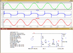
This is a LTSpice simulation of your circuit, its a simple zero crossing detector switch.
The 0.25W resistors are not passing high currents so their wattage rating can be low.

For the sim I have assumed a 230Vac RMS 50Hz supply.
E
 

Attachments

  • AAesp01.gif
    AAesp01.gif
    40 KB · Views: 114
  • Like
Reactions: Jodh

    Jodh

    Points: 2
    Helpful Answer Positive Rating
Status
Not open for further replies.

Similar threads

Part and Inventory Search

Welcome to EDABoard.com

Sponsor

Back
Top