Welcome to our site! EDAboard.com is an international Electronics Discussion Forum focused on EDA software, circuits, schematics, books, theory, papers, asic, pld, 8051, DSP, Network, RF, Analog Design, PCB, Service Manuals... and a whole lot more! To participate you need to register. Registration is free. Click here to register now.
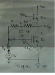
It`s a voltage-controlled voltage feedback for (very) low frequencies - in particular for dc (operating point stabilization).
Frequencies far above the lowpass corner frequency (set by the RC time constant) are not fed back.
During formulation of an answer I have detected an error in my first response. Sorry - it is voltage-controlled current feedback (sometimes called shunt-shunt feedback).
The output voltage drives a current into the the node at the gate where it is superimposed with the current driven by the signal voltage.
Both currents cause a voltage at the gate that controls the output current.
This site uses cookies to help personalise content, tailor your experience and to keep you logged in if you register.
By continuing to use this site, you are consenting to our use of cookies.