Continue to Site

Welcome to EDAboard.com

Welcome to our site! EDAboard.com is an international Electronics Discussion Forum focused on EDA software, circuits, schematics, books, theory, papers, asic, pld, 8051, DSP, Network, RF, Analog Design, PCB, Service Manuals... and a whole lot more! To participate you need to register. Registration is free. Click here to register now.

ICMR simulation from the buffer connection

Status
Not open for further replies.

Junus2012

Advanced Member level 5
Joined
Jan 9, 2012
Messages
1,552
Helped
47
Reputation
98
Reaction score
53
Trophy points
1,328
Location
Italy
Visit site
Activity points
15,235
Hello

Please I would ask why simulating the ICMR from the buffer connection, why does the output is assumed to be related to the input why not to the output

Thank you
 

Hello Junus2012,

I do not understand the question clearly.
But, for a unity gain follower circuit (buffer), the closed loopgain is "1" which means that the output just follows the input.
 

Hello

Yes obviously, but we use this test to observe the ICMR, and my question is why we are sure that the output limitation is due to the ICMR limitation ?? why not due to the limitation in the output transistors ??

Hello Junus2012,

I do not understand the question clearly.
But, for a unity gain follower circuit (buffer), the closed loopgain is "1" which means that the output just follows the input.
 

I might be wrong, but I think the input devices will give up first as the input common mode voltage
is changed beyond the ICMR. Only when the input devices are biased properly, we can expect the output
stage transistors to be working as desired.
 

I might be wrong, but I think the input devices will give up first as the input common mode voltage
is changed beyond the ICMR. Only when the input devices are biased properly, we can expect the output
stage transistors to be working as desired.
Not necessarily. Even for the basic amplifiers it would not hold in one direction.
ICMR for a complete amplifier would be limited both by input as well as output stages. If you see some sources pointing otherwise, please share.
 

What about if the op-amp has a rail to rail input stage, in this case the output will be giving up first and the measurement will fail

I might be wrong, but I think the input devices will give up first as the input common mode voltage
is changed beyond the ICMR. Only when the input devices are biased properly, we can expect the output
stage transistors to be working as desired.
 

... simulating the ICMR ..., why ... related to the input why not to the output
What about if the op-amp has a rail to rail input stage, in this case the output will be giving up first and the measurement will fail

I think the discussion runs into the wrong direction: the ICMR analysis should be carried out as a small signal test; with a well-designed amp the output should be far from any limitation. Here's an image from a Cādence tutorial, where the ICMR is (arbitrarily) defined for max_gain/2 : View attachment ICMR.pdf
 
Dear Mr. Erikl :)

I believ with the method you showed in your attachment and I always use this setup to find the ICMR and it gives the accurate value, any way it is new for me to see that in your attachement are considering the range from the -6 dB from the maximum gain and I dont know why ????

However, the main problem of me is finding the ICMR from the buffer method, yes as you said the op-amp must be under the small signal conditionand this is for sure afforded by the buffer feedback connection. please consider this method and if it is possible to tell me how the output is given the limitation of the input common mode range, why not this limitation is due to the output stage ???

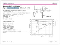
I haveattached you the page from the Allen Holberg book about this test to refer to it


Thank you in advance


I think the discussion runs into the wrong direction: the ICMR analysis should be carried out as a small signal test; with a well-designed amp the output should be far from any limitation. Here's an image from a Cādence tutorial, where the ICMR is (arbitrarily) defined for max_gain/2 : View attachment 86285
 

... it is new for me to see that in your attachement are considering the range from the -6 dB from the maximum gain and I dont know why ????
Hello Senan-Junus ;-)
as I told you above: the -6dB value is totally arbitrary. You can use any value from max_gain -1%, -10%, -3dB, -6dB, -20dB ... there's no standard, it just depends on your own accuracy requirement! Just tell this value together with the measured ICMR.

However, the main problem of me is finding the ICMR from the buffer method, yes as you said the op-amp must be under the small signal conditionand this is for sure afforded by the buffer feedback connection. please consider this method and if it is possible to tell me how the output is given the limitation of the input common mode range, why not this limitation is due to the output stage ???

I have attached ... the page from the Allen Holberg book about this test to refer to it

I'm sorry (Mr. Allen & Mr. Holberg) IMHO this Subckt. is a bad example for an opAmp in buffer configuration - it has a very bad common mode rejection (CMR): a well-designed opAmp in this configuration does not change its output voltage (so much) within the ICMR: Vout=Vin for a good buffer!

For such a bad CMR opAmp of course the output limitation also limits the applicability of the ICMR, but literally it is not an ICMR limitation (the "I" means "input"!): the ICMR should only depend on input voltage limitations - at least for a buffer configuration.
 
Last edited:
Hello Erikl

still you remember my old name, I think you know me personally... perhaps who knows :)

Any way, could you please give me the answer of this,
if an op-amp with an output signal range of 0.5 V above and below the supply rails. it has a rail-to-rail input stage. in the buffer connection ICMR setup test, the output should follow the input for the whole voltage supply rail range as it rail to rail circuit. However Mr. Erikl, since the output has the limits of 0.5 V, this will cause the output of the ICMR test to have non linearity at 0.5 V above and below the supply rail.

What I conclude from this example that this method is not suitable if the output limitation is below the input limitation,
I need your confirmation about this idea or if you have a different opinion.

I am sorry if I wrote too much, but you know me, this is my habit :):)


Hello Senan-Junus ;-)
as I told you above: the -6dB value is totally arbitrary. You can use any value from max_gain -1%, -10%, -3dB, -6dB, -20dB ... there's no standard, it just depends on your own accuracy requirement! Just tell this value together with the measured ICMR.


I'm sorry (Mr. Allen & Mr. Holberg) IMHO this Subckt. is a bad example for an opAmp in buffer configuration - it has a very bad common mode rejection (CMR): a well-designed opAmp in this configuration does not change its output voltage (so much) within the ICMR: Vout=Vin for a good buffer!

For such a bad CMR opAmp of course the output limitation also limits the applicability of the ICMR, but literally it is not an ICMR limitation (the "I" means "input"!): the ICMR should only depend on input voltage limitations - at least for a buffer configuration.
 

if an op-amp with an output signal range of 0.5 V above and below the supply rails. it has a rail-to-rail input stage. in the buffer connection ICMR setup test, the output should follow the input for the whole voltage supply rail range as it rail to rail circuit. However Mr. Erikl, since the output has the limits of 0.5 V, this will cause the output of the ICMR test to have non linearity at 0.5 V above and below the supply rail.

Yes that's true. But I wouldn't necessarily call it an ICMR limitation, because the ICMR isn't responsible for this limitation.

What I conclude from this example that this method is not suitable if the output limitation is below the input limitation
Totally agree!

I am sorry if I wrote too much, but you know me, this is my habit :):)
That's also true ;-), but it's always better to describe a problem thoroughly!
 
Thank you in advance Erikl.

I will follow of course your confirmation,

I just want to clear about what you said "Yes that's true. But I wouldn't necessarily call it an ICMR limitation, because the ICMR isn't responsible for this limitation"

obviously it is not responsible, but it would effect the measurement of the ICMR. However you have also cleared that later

Thank you once again
see you with another post :)

Yes that's true. But I wouldn't necessarily call it an ICMR limitation, because the ICMR isn't responsible for this limitation.

Totally agree!


That's also true ;-), but it's always better to describe a problem thoroughly!
 

Status
Not open for further replies.

Part and Inventory Search

Welcome to EDABoard.com

Sponsor

Back
Top