Continue to Site

Welcome to EDAboard.com

Welcome to our site! EDAboard.com is an international Electronics Discussion Forum focused on EDA software, circuits, schematics, books, theory, papers, asic, pld, 8051, DSP, Network, RF, Analog Design, PCB, Service Manuals... and a whole lot more! To participate you need to register. Registration is free. Click here to register now.

ICD2 Clone 16F876A with MPLAB 7.6 Working !!!

Status
Not open for further replies.

charith

Junior Member level 2
Joined
May 26, 2007
Messages
23
Helped
1
Reputation
2
Reaction score
1
Trophy points
1,283
Activity points
1,441
mplab 7.6

Dear all,

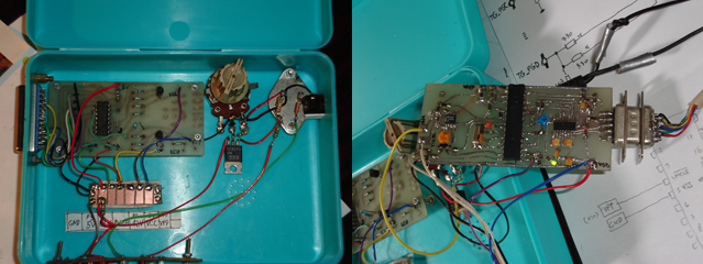
I have tested the Lothar Stolz's ICD2 Debugger with some modifications and it's working with MPLAB 7.6 (latest) without any problem.

I'm using the following bootloader. ICD2_760A
 

mplab icd2 clone

Can you post the schematic? What's the different between this one and the one with PIC16F877 or 16F877A?
 

mplab 7.6 download

funnynypd said:
Can you post the schematic? What's the different between this one and the one with PIC16F877 or 16F877A?

Yes, there's no difference between 16F877A and 16F876A. Boot loader is the patched version and works perfectly with MPlab 7.6

Attached the schematic file (.pdf)
 
icd2 clone 16f876a

Thanks for sharing!
 

programmer 16f876a

thanks for the sharing
 

differences between 16f876 and 16f876-04

Very thanks for sharing I am going to try it tomorrow
 

icd2_760a download

I know this mag is old but can u help me because I built your ckt but that can't able to udentify a device.

thanks in advance
 

16f876 load hex

try this guidelines when connecting the ICD2 with PC.

i. First Connect the Power jack supplying DC 13V or above (Not more than 25V)
ii. Go to Device Manager and go to serial port properties. Under advanced settings put the FIFO levels into minimum. (Do not Disable FIFO buffering) and select Hardware flow control
iii. Now restart to take changes effect
iv. Start MPLAB IDE
v. You can view the Vdd and Vpp voltages from MPLAB
vi. This device can be operated in two modes.
a. Programming mode – Chips can be programmed, Erased, Read etc
b. Debugging mode ‐ Chips can be programmed and debug real time and animate step by step
vii. For programming mode Programmer > Select Programmer > MPLAB ICD2 and if debugging is used Debugger > Select Tool > MPLAB ICD2
viii. Under selected mode select MPLAB ICD2 Setup Wizard. Select the COM port where the device is connected and select a higher baud rate (19200 and 57600 baud rates are working) and finish the wizard
ix. If first time using, before do anything select Download ICD2 operating system and wait until it says Connected in the output window
x. Put the desired Microcontroller on the ZIF socket according to the device insertion position diagram (or you can use ICSP connector)
xi. Load the hex file or if it’s written in Mplab IDE just compile. Program will be automatically loaded on to the memory.
xii. Select Connect and it will detect the attached microcontroller.
xiii. Now program with the code.
xiv. For Debugger, the steps are almost same. Refer to ICD2 user manual for more details.

Hope this will help you in correctly connecting the IDC2

nimarc said:
I know this mag is old but can u help me because I built your ckt but that can't able to identify the device.

thanks in advance
 

mplab download

Why would you suggest not disabling the FIFO buffers as MPLAB suggests? (also a reboot is needed)
 

icd2_760a

If the FIFO is at maximum the connection would not be established. If the FIFO is disabled some PC's will give errors while connecting. Most of the cases Minimum level of FIFO would work.

To take the settings to take effect you must restart. (if only you have changed the FIFO settings)

blueroomelectronics said:
Why would you suggest not disabling the FIFO buffers as MPLAB suggests? (also a reboot is needed)
 

I'v build it using attachment. I'm using PIC16F876A and it is working like a charm.
Also i'v connected it in MPLAB v 8.46, downloaded firmware, and it is working.
I am using LM317 for a voltage stabilising, so i tweak it to get 15v for VPP. Also I get voltage readings of VPP, VDD and TG_MCLR in MPLAB. Just a hunch for builders. Try to keep short cables between programmer and chip or board because i have problems programming it and finaly i found that i have some kind of interference from my soldering station. I shut it down and all is working fine. This design is very good so thank you very much for attachment. On the first picture is AN589 parallel programmer and on the second is ICD2. Sory for bad english and thanks again fo schematic. Greetings from Croatia :)


Glad to hear the comments from you. Cheers!!!


techovski said:
I'v build it using attachment. I'm using PIC16F876A and it is working like a charm.
Also i'v connected it in MPLAB v 8.46, downloaded firmware, and it is working.
I am using LM317 for a voltage stabilising, so i tweak it to get 15v for VPP. Also I get voltage readings of VPP, VDD and TG_MCLR in MPLAB. Just a hunch for builders. Try to keep short cables between programmer and chip or board because i have problems programming it and finaly i found that i have some kind of interference from my soldering station. I shut it down and all is working fine. This design is very good so thank you very much for attachment. On the first picture is AN589 parallel programmer and on the second is ICD2. Sory for bad english and thanks again fo schematic. Greetings from Croatia :)


Status
Not open for further replies.

Similar threads

Part and Inventory Search

Welcome to EDABoard.com

Sponsor

Back
Top