SUDOsarvesh
Newbie
Hello TechGeeks,
Please welcome me to here as this is my first query on EDA Forum, and Kudos to you all for gathering impressive forum here.
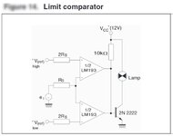
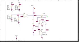
Query goes like this: "Trying to develop a HW feature as Overvoltage protection and Undervoltage protection on 12V net with the help of LM2903YPT (Link Datasheet) comparator IC. I have tried to adapt limit comparator for this feature (see LimitComparator.jpg). Ahead of this circuit I have added positive feedback to these comparators but it seems like hysteresis is only possible on UVLO not OVLO (see Circuit.jpg). There is no affect of resistive +ve feeback on OVLO IC.
[Note:] In Circuit.jpg the top LM2903 is for UVLO and bottom LM2903 is for OVLO.
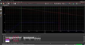
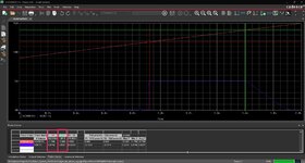
Observations: In simulation results, the red rising and falling signal is 12V which needs to be monitored via 5V reference voltage, the blue signal is output of collective LM2903, 5V on normal range of 12V net and Zero on Undervoltage and Overvoltage of 12V net. And there are one red cursor(Y1) for UVLO and green cursor(Y2) OVLO activation value. If you look on 12VRising_simulation.jpg and 12VFalling_simulation.jpg, you will find we have hysteresis of 800mV on UVLO but for OVLO there is no.
Question:
1. I am getting UVLO proper with hysteresis but OVLO is ramped on activation if you see simulation results, How is it possible to make it step activation?
2. How is it possible to provide hysteresis on OVLO side?"
Thank you!
Please welcome me to here as this is my first query on EDA Forum, and Kudos to you all for gathering impressive forum here.
Query goes like this: "Trying to develop a HW feature as Overvoltage protection and Undervoltage protection on 12V net with the help of LM2903YPT (Link Datasheet) comparator IC. I have tried to adapt limit comparator for this feature (see LimitComparator.jpg). Ahead of this circuit I have added positive feedback to these comparators but it seems like hysteresis is only possible on UVLO not OVLO (see Circuit.jpg). There is no affect of resistive +ve feeback on OVLO IC.
[Note:] In Circuit.jpg the top LM2903 is for UVLO and bottom LM2903 is for OVLO.
Observations: In simulation results, the red rising and falling signal is 12V which needs to be monitored via 5V reference voltage, the blue signal is output of collective LM2903, 5V on normal range of 12V net and Zero on Undervoltage and Overvoltage of 12V net. And there are one red cursor(Y1) for UVLO and green cursor(Y2) OVLO activation value. If you look on 12VRising_simulation.jpg and 12VFalling_simulation.jpg, you will find we have hysteresis of 800mV on UVLO but for OVLO there is no.
Question:
1. I am getting UVLO proper with hysteresis but OVLO is ramped on activation if you see simulation results, How is it possible to make it step activation?
2. How is it possible to provide hysteresis on OVLO side?"
Thank you!