expelleior
Member level 1
hi,
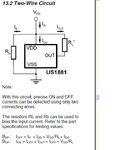
I want to use hall effect on bike wheel but not sure how to use it. Is a 10k resistor between 5+ and output all that is needed ? (pins 1 and 3)
will it toggle to ground/zero while connected to 5+ ?
this blurb was on the site which has the sensor:
Posted by Marcwolf on 15th Jun 2010
Bit of an application note for the unwary
Looking from the front where the writing is
Pins run from left to right 1,2,3
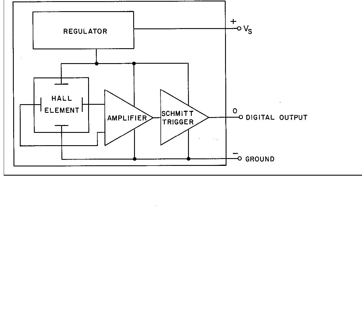
Pin 1 is +5v (or +3.3v)
Pin 2 is Gnd
Pin 3 is Output
Put a 10K resistor between pins 1 & 3. The output will then toggle between High and Low with the magnet. Upi can feed that directly onto a digital pin of a PicAxe or Arduino }}
**broken link removed**

I want to use hall effect on bike wheel but not sure how to use it. Is a 10k resistor between 5+ and output all that is needed ? (pins 1 and 3)
will it toggle to ground/zero while connected to 5+ ?
this blurb was on the site which has the sensor:
Posted by Marcwolf on 15th Jun 2010
Bit of an application note for the unwary
Looking from the front where the writing is
Pins run from left to right 1,2,3
Pin 1 is +5v (or +3.3v)
Pin 2 is Gnd
Pin 3 is Output
Put a 10K resistor between pins 1 & 3. The output will then toggle between High and Low with the magnet. Upi can feed that directly onto a digital pin of a PicAxe or Arduino }}
**broken link removed**