bcro
Newbie level 6
My question really is about as general as the title indicates, but here's the specific context:
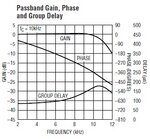
In the lab we often need to digitize spectroscopy signals, which consist of a string of more or less Gaussian pulses. The shape and spacing of these pulses are what we measure (we often fit curves to them in the computer). I'm trying to design some anti-aliasing filters, and it would be very convenient to use the LTC 1564. I'm attaching a snippet of the spec sheet that shows the change in group delay over frequency:

I'm realizing I just don't have enough experience with such things to look at that plot and decide if I should worry about distorting my pulse shapes. Lets say I'm conservative, and keep my signals down around 1/2 the stated cutoff frequency. Does a variation of 25 microSeconds over that range translate into a measurable difference in the pulse coming out of the filter? How does one go about answering such questions?
Thanks in advance for your help. Have a great day.
--Brad
In the lab we often need to digitize spectroscopy signals, which consist of a string of more or less Gaussian pulses. The shape and spacing of these pulses are what we measure (we often fit curves to them in the computer). I'm trying to design some anti-aliasing filters, and it would be very convenient to use the LTC 1564. I'm attaching a snippet of the spec sheet that shows the change in group delay over frequency:

I'm realizing I just don't have enough experience with such things to look at that plot and decide if I should worry about distorting my pulse shapes. Lets say I'm conservative, and keep my signals down around 1/2 the stated cutoff frequency. Does a variation of 25 microSeconds over that range translate into a measurable difference in the pulse coming out of the filter? How does one go about answering such questions?
Thanks in advance for your help. Have a great day.
--Brad