Continue to Site

Welcome to EDAboard.com

Welcome to our site! EDAboard.com is an international Electronics Discussion Forum focused on EDA software, circuits, schematics, books, theory, papers, asic, pld, 8051, DSP, Network, RF, Analog Design, PCB, Service Manuals... and a whole lot more! To participate you need to register. Registration is free. Click here to register now.

How to simulate the CMRR of a fully diff OpAmp?

Status
Not open for further replies.

Fabien

Full Member level 1
Joined
May 22, 2011
Messages
96
Helped
10
Reputation
20
Reaction score
10
Trophy points
1,288
Location
Grenoble
Activity points
2,025
Hello all,

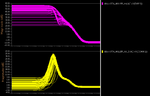
I'm would like to know how to simulate the CMRR of a fully diff OpAmp. The right thing to do is an MC simulation and look at the output differential mode. But, since we should simulate for differential input (AC) and common-mode input (AC), it means 2 different simulations which will not correspond to each other.
Any idea how to perform this kind of sims?

Thank you
 

hi,

Simply set two AC sources at the inputs of the diff amp and set the phase of these sources as same

And measure the gain at the output .... this is your common mode gain "Acm"

then set the pahse difference for the inputs 0 and 180 correspondingly and measure the gain..

This is your differential gain "Adiff"

Then just divide the diferential gain by common mode gain.. that is "Adiff/Acm"
Thanks...
 

sure!
But it means 2 different simulations. As I need to run Monte Carlo simulation for mismatch, I don't think I'll get the same results for 2 different runs! Maybe I'm wrong??
 

Hi fabien,

I have an Idea.. and let me know if it works..

Use two opamps one for Acm and another for Adiff ... and get the values of Acm and Adiff from calculator..

And make an expression of CMRR = Adiff/Acm .....
then run Monte carlo simulation....

or see this video.. and i am also working in this .... i will let you know if i get anyhting..

https://www.youtube.com/watch?v=1ipHd8cV8Bc

thanks...
 

OK,

I simulate 2 identical OpAmp, with the same input signals (differential input). I run MC simulation, and I got different results (I check output differntial)! For sure, this test bench could not work for CMRR simulation. The simulator probably do mismatches randomly.

If you have any other idea, you'r welcome.

Thanks
 

Hi,

Its due to the MC deviation file and it depends on the pdk and the technology..

Did you see the video link that i have posted... i think it will help you somewhat..

and let me know if you have doubts..
Thanks
 

Thank you for your answer.
I tried a parametric simulation, like the video you posted. But, with a Monte Carlo simulation, I'm not sure it's working. I test a DC current in a resistor and check the DC voltage. Unfortunately, for the 2 parametric simulations, the results are different. So, the Common Mode Gain of the OpAmp (for example at the third MC run) doesn't correspond to the Commun Mode Gain of the OpAmp at the third MC sim.
Maybe this kind of CMRR extraction is wrong...

Thanks.
 

Fabien,

I think your results are suffering from bad statistics: due to the random parameter selection by the MC method, you can't expect a good conformance between the 2 opAmp results for only a few (3 or 10 ?) MC runs. Statistics tell that the conformance (statistically!) is about √N/N (N is the number of runs), i.e just ≈32% for 10 runs.

If you could spend the time for 100 runs, you'd achieve about 10% conformance (let's say: for CMRRmax & CMRRmin).

erikl
 

Thank you, I think I understand!
But, I thought (thanks to the video) with a parametric analysis, the first run will have the same properties for the common mode analysis than the first run for the differential mode analysis. So a good way to determined the CMRR of the opamp.
What you suggest is to run a lot of simulations for common mode and differential mode (input). For the CMRR_{max}, it's quite high (same results with no MC run) the differential gain is around 60dB and common mode gain around 0. For the CMRR_{min}, unfortunately it's quite low, the lowest differential gain is around 10dB and the highest common mode gain is around 10dB. So here is my question: is it possible to have 10dB for the DM Gain and 10dB for CM Gain? Could we have the same parameter selection for 2 different runs (AC analysis of differential mode Input and common mode input)? Or is the typical way to find the CMRR of an OpAmp by simulating 2 different MC run?
May be I should conclude my OpAmp is quite bad for common mode rejection!

Thank you
 

Here are the plots: The differential mode gain from 21 to 57dB and the common mode gain from -2 to 7.7dB:

So it means the CMRR is from 60dB to 13dB!??
 

Attachments

  • MC_MD_Gains.png
    MC_MD_Gains.png
    11.3 KB · Views: 131

I can see you have almost 40 dB of variation over MC runs.. it seems quite strange, in differential mode. And the rejection of your common mode is really poor. You should check your design, especially OP over different runs. Are you adding only mismatch variations or also process variations?
 
  • Like
Reactions: Fabien

    Fabien

    Points: 2
    Helpful Answer Positive Rating
Are you adding only mismatch variations or also process variations?

I think the Monte Carlo I'm running takes everything into account (Process, mismatch... ). The transistor lengths are not the smallest in order to decrease the mismatch.
Here is the schematic with transistor length. For the CMRR simulation, the CMFB circuit (Switched capactors CFMB) is disabled so all the TOP transistors are biased to the same voltage Vb1.
I check the DC variation, for the VM and VP the variation is between 0.75 and 0.795V. But VM follows the VP variation. But this is not the case for VoutP and VoutM. These two points are in the top or bottom level (gnd; Vdd) or separately one close to Vdd the other close to gnd! I think the trouble is here. Does it mean the biasing point (Vb1) is bad? It's between 1.53 and 1.63V (only 100mV of variation).

Thank you for your expertise!
 

Attachments

  • Current_mirror_OTA.png
    Current_mirror_OTA.png
    34.8 KB · Views: 168

So here is my question: is it possible to have 10dB for the DM Gain and 10dB for CM Gain?
Sure, if the operation point slips into a bad region (one or more transistors in triode region). You should care for DC gain=1 feedBack, see the foll. tutorial: View attachment opAmp_CMRR_sim.pdf. And think about the right common mode range: View attachment Aol_vs_CMR.pdf.

... I thought (thanks to the video) with a parametric analysis, the first run will have the same properties for the common mode analysis than the first run for the differential mode analysis. So a good way to determined the CMRR of the opamp.

Could we have the same parameter selection for 2 different runs (AC analysis of differential mode Input and common mode input)?
I think this should be possible with a single testBench with both opAmp setups. Perhaps this Cādence tutorial may be helpful:
 

Attachments

  • Cadence_Monte_Carlo_simulation_tutorial.pdf
    1,009.3 KB · Views: 126

Status
Not open for further replies.

Part and Inventory Search

Welcome to EDABoard.com

Sponsor

Back
Top