Continue to Site

Welcome to EDAboard.com

Welcome to our site! EDAboard.com is an international Electronics Discussion Forum focused on EDA software, circuits, schematics, books, theory, papers, asic, pld, 8051, DSP, Network, RF, Analog Design, PCB, Service Manuals... and a whole lot more! To participate you need to register. Registration is free. Click here to register now.

[SOLVED] how to perform ac analysis in candence for an inverter?

Status
Not open for further replies.
is a kind of joke ??
put it in closed loop, and use .AC or STB,
your simple inverter is for sure stable
:)
 

is a kind of joke ??
put it in closed loop, and use .AC or STB,
your simple inverter is for sure stable
:)

Dude this forum is full of beginners if they are not good enough for you just do not answer

---------- Post added at 12:44 ---------- Previous post was at 12:39 ----------

Hi guys

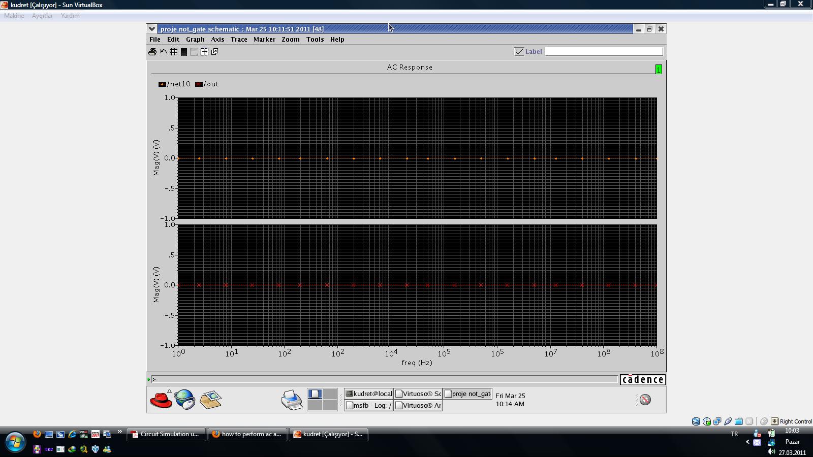
I want to know how to perform an ac analysis for an inverter or any other designes?
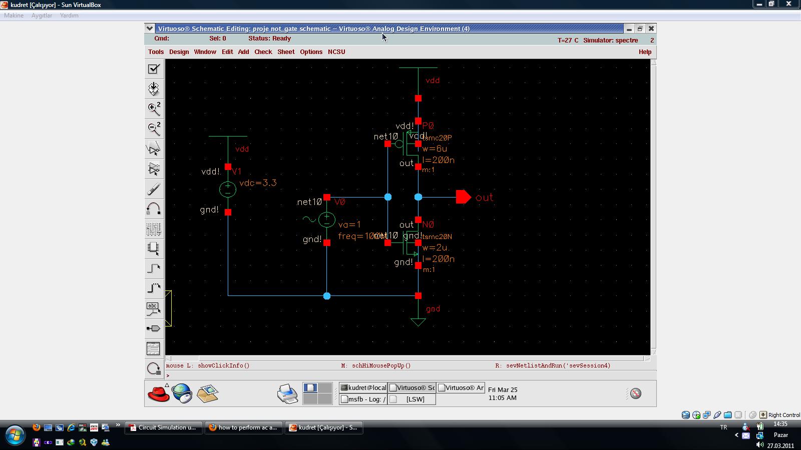
this is my inverter ;)

ImageShack® - Online Photo and Video Hosting

Hi kudret

all you need to perform a .AC analysis (in an open or closed loop configuration) is to use a voltage source at the input with AC amplitude set to 1V. The DC amplitude field of the same source can be used to set the OP around which the small signal analysis is valid.

In your simulator then you choose the frequency range within which you perform the analysis

Ask if you need more details
 

You might however ask yourself if a small signal analysis is
useful for a large signal switching circuit that may never
see the operating point of analysis.

Although I have seen and used inverters applied linear, that's
kind of a fringe application.

You can connect output to input through an iprobe block
and get the stability / gain / phase plots you want. But
whether they tell you anything ultimately useful is another
matter.
 

The opening post did not require a stability analysis; why insisting on having the analysis carried out in a closed loop configuration? as long as the DC level of input and output node are initialized the AC analysis will have meaning

Even if this were not a real world application (which you are disputing yourself), it is still good enough to learn how to run an AC analysis.

You will get what's the gain and phase delay for small signals around your OP, how is that not good enough?
 

Dude this forum is full of beginners if they are not good enough for you just do not answer

---------- Post added at 12:44 ---------- Previous post was at 12:39 ----------


Hi kudret

all you need to perform a .AC analysis (in an open or closed loop configuration) is to use a voltage source at the input with AC amplitude set to 1V. The DC amplitude field of the same source can be used to set the OP around which the small signal analysis is valid.

In your simulator then you choose the frequency range within which you perform the analysis

Ask if you need more details

thanks for your answers dgnani (both of them:) ) actually I want to plot frequeceny response of an inverter.

I found this file and did same settings but it didn't work.

Hotfile.com: Hébergement de fichiers par un clic: Circuit Simulation using Spectre.pdf
 

What among TRAN, DC and AC analysis did not work?

I have to say that the description of the AC analysis is a bit iffy, you do not need a vsin source to run an AC analysis... still it should work as long as you have set in it some value for 'DC Amplitude'
 

What among TRAN, DC and AC analysis did not work?

I have to say that the description of the AC analysis is a bit iffy, you do not need a vsin source to run an AC analysis... still it should work as long as you have set in it some value for 'DC Amplitude'

just ac analysis did not work, others ok
 

did u set AC amplitude in the vsin sourve to 1V?

what results did you get?

what did not work?
 

It looks to me like your output is shorted to the input... plot both magnitude and phase of the output and increase the frequency range to 1GHz, make sure your input DC Amplitude is set somewhere midrail, and post a plot of the simulation of the annotated simulation schematic (larger than the last one)
 

no it is not shorted.

for vsin;
frequency=100Mhz
AC amp=1V
DC amp=3V

for simulation;
sweep variable:frequency
sweep range: start=1 stop=1G
sweep type:logarithmic
points per decade=10

here is the shematic and results

 
Last edited:

move the DC Amplitude of the input source to say 1.5V and post the netlist file and simulation log
 

this is the log, what about the netlist?
 

thanks dgnani for your help
i did it, it was just about frequency range, 1Ghz is not enough to see ac response in 0.18um.
 

Status
Not open for further replies.

Part and Inventory Search

Welcome to EDABoard.com

Sponsor

Back
Top