kabaleevisu
Advanced Member level 2
- Joined
- Apr 14, 2010
- Messages
- 616
- Helped
- 85
- Reputation
- 170
- Reaction score
- 81
- Trophy points
- 1,308
- Location
- Chennai,India
- Activity points
- 4,512
hi all ,
i have the board file which containt impedace 50E ,90E ,100E , for differential pair trace width is kept as 4.5 mil i have some clarification about impedance matching
1.how to choose the trace width for impedance 50E ,90E ,100E ??
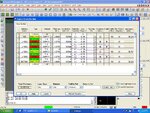
2. setup --- > cross section impedance is change when i changing trace for example i choose 100E trace width is (for differential pair )0.502mil only but in constraint manager kept as (for differential pair ) 4.5mil ,how it is come ?? i could not understand
3.what is reason to choosing negative artwork only in plane layer
please give me the suggestion to me


i have the board file which containt impedace 50E ,90E ,100E , for differential pair trace width is kept as 4.5 mil i have some clarification about impedance matching
1.how to choose the trace width for impedance 50E ,90E ,100E ??
2. setup --- > cross section impedance is change when i changing trace for example i choose 100E trace width is (for differential pair )0.502mil only but in constraint manager kept as (for differential pair ) 4.5mil ,how it is come ?? i could not understand
3.what is reason to choosing negative artwork only in plane layer
please give me the suggestion to me


Attachments
Last edited:
