Continue to Site

Welcome to EDAboard.com

Welcome to our site! EDAboard.com is an international Electronics Discussion Forum focused on EDA software, circuits, schematics, books, theory, papers, asic, pld, 8051, DSP, Network, RF, Analog Design, PCB, Service Manuals... and a whole lot more! To participate you need to register. Registration is free. Click here to register now.

How to inteprete this Mealey State Diagram?

Status
Not open for further replies.

student2005

Member level 3
Joined
Sep 23, 2005
Messages
57
Helped
2
Reputation
4
Reaction score
1
Trophy points
1,288
Activity points
1,793
input output diagram using toilet

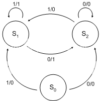
Don't know why, whenever I come to this kind of state diagram, I don't understand it. Possible to explain in plain language? Thanks.

Mealymachine_jaredwf.png
 

mealey diagramm

They have X / Y values where
X : value of input
Y : value of output
Note that states and outputs are different signals. States are stored in registers, while outputs are a function of states and inputs (ie they are formed from a combinational circuit fed with states and inputs).
 

mealey state machine

In this diagram parts of a rest state (S0), it is very common to include an initial state in these machines, if it once give account you uprooted the robot, does not become to this state.
Based on the value of the entrance you pass to a state or another one, thus if he is a "1" you happen to S1 and if he is a "0" you happen to S2.
In the S1 state the machine is while the entrance is equal to "1", putting the exit to "1" (for that reason the arrow is born and dies in the same one circle) and if a "0" in the entrance takes place, passes to the S2 state, fixing the exit to "1". The other part of the diagram is completely analogous.
 

mealey diagrama

Possible to use this kind of state to design an asynchronous counter? Thanks.
 

fsm mealy 1011101

Hi,

We Can Interpret that state machine as follows:-

The System Could be in 3 states <i.e we are having 2 storage elements (FF) with their Q's represnt the state>....we have one isolated state.

Now if we are in State S0 : if we get '1' as an input we move to State S1 and set the output to '0'.else if we get '1' as an input we move to State S2 and set the output to '0'.

if we are in State S1 : if our input is '0' we will go to state S2 and set output to '1'
elsif input is '1' we will remain in the same state and set output to '1'

if we are in State S2 : if our input is '0' we will remain in state S2 and set output to '0' elsif input is '1' we will remain in the same state and set output to '0'

For a good design we should account for the last state S3, it shouldn't be isolated to have a self starting SM, otherwise we may stay there forever.

Hope that helped.

Samer El-Saadany
 

Status
Not open for further replies.

Similar threads

Part and Inventory Search

Welcome to EDABoard.com

Sponsor

Back
Top