Continue to Site

Welcome to EDAboard.com

Welcome to our site! EDAboard.com is an international Electronics Discussion Forum focused on EDA software, circuits, schematics, books, theory, papers, asic, pld, 8051, DSP, Network, RF, Analog Design, PCB, Service Manuals... and a whole lot more! To participate you need to register. Registration is free. Click here to register now.

How to generate a simple c- code

Status
Not open for further replies.

emanuelpic

Newbie level 4
Joined
Jul 1, 2009
Messages
7
Helped
0
Reputation
0
Reaction score
0
Trophy points
1,281
Location
Malaysia
Activity points
1,345
Hi everybody. I am doing an inverter based on PIC 16f877A microcontroller and I am facing a problem in C code how to generate the SPWM using ccp1 from PIC.
my carrier frequency is 2000khz, and it is supplied to H-bridge.
Any body can help me to generate a simple C- code. I appreciate your cooperation
 

Re: SPWM inverter using PIC16f877A

Dear emanuelpic ,
NOW, I work on the same subject and I met the same problem, if you have solved the problem, please do you can give me the code in c that you used in your project?
 

Re: SPWM inverter using PIC16f877A

i think you need to visit tahmid blog you will see what you are looking for
 

Re: SPWM inverter using PIC16f877A

I hope the following will be helpful.


my code for init

Code C - [expand]
1
2
3
4
5
6
7
8
9
10
11
12
13
14
15
16
17
18
19
20
21
22
23
24
25
26
27
28
29
30
31
32
33
34
35
36
37
38
39
40
41
42
43
44
45
46
47
48
49
50
51
52
53
54
55
56
57
58
59
60
61
62
63
64
65
66
67
68
69
70
71
72
73
74
75
76
77
78
79
80
81
82
83
84
85
86
87
88
89
90
91
92
93
94
95
96
97
98
99
100
101
102
103
104
105
106
107
108
109
110
111
112
113
114
115
116
117
118
119
120
121
void CCP_start()
{
 
    sin_am=0.2000;//sin函数的幅值
    crut_ie=1;//电流慢保护允许
    sin_up=1;//正负半周SIN函数
    sin_num=0;//脉宽周期调整计数器
    TMR2ON=0;
    TMR1CS=0;//同步模式
    T1SYNC=0;//内部指令周期
    T1CKPS1=T1CKPS0=0;
    TMR1H=0XF9;
    TMR1L=0XB2;//定时器1初值
    TOUTPS3=0;TOUTPS2=0;TOUTPS1=0;TOUTPS0=0;//定时器2后分频器5分频
    //复位ccp
    //CCP2M3=0;CCP2M2=0;CCP2M1=0;CCP2M0=0;
    CCP1M3=0;CCP1M2=0;CCP1M1=0;CCP1M0=0;
    GIE=0;PEIE=0;//禁止总中断和外围中断
    
    CCP2IF=0;
    CCPR2L=0X0;//设置80%的脉宽输出
    CCP2X=CCP2Y=0;
    CCP2M3=CCP2M2=1;//PWM模式
    PR2=0Xff;//设置PWM的工作周期,20mhz,PWM周期=(PR2+1)*4*TOSC*TIMER2预分频比=19.531khz
    
    //-------
    CCP1IF=0;
    CCPR1L=0X00;//设置80%的脉宽输出
    CCP1X=CCP1Y=0;
    CCP1M3=CCP1M2=1;//PWM模式
    PR2=0Xff;//设置PWM的工作周期,20mhz,PWM周期=(PR2+1)*4*TOSC*TIMER2预分频比=19.531khz
    T2CKPS1=T2CKPS0=0;//timer2预分频器1
    TOUTPS3=TOUTPS2=TOUTPS1=TOUTPS0=0;//后分频器1
    //-------------------
    CCP2IE=1;
    TMR1ON=1;
    TMR2ON=1;
    TMR1IE=1;//定时器1中断使能   
    //-----
    
    PEIE=1;//外围模块中断使能
    TMR2IE=0;//打开定时器2中断使能
    GIE=1;
}


and my code for interrupt
void interrupt key_ccp_timer()
{
    if(TMR2IF&TMR2IE)
    {
        TMR2IF=0;//定时器2中断服务函数
        
    }
 
    if(RBIF&&RBIE){RBIF=0;if((!RB6)&&power_ie)k=1;}//端口b中断服务函数
    if(TMR1IF&TMR1IE)
    {
        TMR1IF=0;
        TMR1H=0XF9;
        TMR1L=0XB2;//定时器1初值
        //tm_sum++;if(tm_sum==31){tm_sum=0;tmr_s=!tmr_s;tmr_d=1; }
        if(sin_num==32)
        {
            sin_num=0;sin_up=!sin_up;
            if(sin_up)
            {
                CCP2IF=0; 
                CCPR2L=0X00;//设置80%的脉宽输出
                CCP2X=CCP2Y=0;
                CCP2M3=CCP2M2=1;//PWM模式
                PR2=0Xff;//设置PWM的工作周期,20mhz,PWM周期=(PR2+1)*4*TOSC*TIMER2预分频比=19.531khz 
            }
            else
            {
                //-------
                CCP1IF=0;
                CCPR1L=0X00;//设置80%的脉宽输出
                CCP1X=CCP1Y=0;
                CCP1M3=CCP1M2=1;//PWM模式
                PR2=0Xff;//设置PWM的工作周期,20mhz,PWM周期=(PR2+1)*4*TOSC*TIMER2预分频比=19.531khz
                //-------------------
                    
            }
        }
        
        sin_d=sin_[sin_num];    
        sin_l=sin_am*sin_d;if(sin_l>=255)sin_l=255;//限幅
        if(sin_num>15)
        { 
            if(sin_l>180)sin_l-=30;
            else if(sin_l>120)sin_l-=20; 
            else if(sin_l>60)sin_l-=10;
        }
 
        if(sin_up)                        
        {
            
        
            //-------
            CCP1IF=0;
            CCPR1L=(unsigned char)sin_l;//设置80%的脉宽输出
            CCP1X=CCP1Y=0;
            CCP1M3=CCP1M2=1;//PWM模式
            PR2=0Xff;//设置PWM的工作周期,20mhz,PWM周期=(PR2+1)*4*TOSC*TIMER2预分频比=19.531khz
            //-------------------
        }//换向
        else 
        {
            CCP2IF=0;
            CCPR2L=(unsigned char)sin_l;//设置80%的脉宽输出
            CCP2X=CCP2Y=0;
            CCP2M3=CCP2M2=1;//PWM模式
            PR2=0Xff;//设置PWM的工作周期,20mhz,PWM周期=(PR2+1)*4*TOSC*TIMER2预分频比=19.531khz
        
        }//换向
        sin_num++;
    }
    //定时器1中断服务函数
}

 
Last edited by a moderator:

Re: SPWM inverter using PIC16f877A

Hello Tahmid,I read your blog but I am having a problem of generating the frequency different to 50Hz I want ot control my H_Bridge with the frequency of 28KHz.

can you please help with calculations.

Thanks.
 

Re: SPWM inverter using PIC16f877A

Hello Tahmid,I read your blog but I am having a problem of generating the frequency different to 50Hz I want ot control my H_Bridge with the frequency of 28KHz.

can you please help with calculations.

Thanks.

You can find all the calculations here:

Demystifying The Use of Table Pointer in SPWM - Application in Sine Wave Inverter
https://tahmidmc.blogspot.com/2013/02/demystifying-use-of-table-pointer-in.html

Hope this helps.
Tahmid.
 

Re: SPWM inverter using PIC16f877A

Hello Tahmid those calculations are not giving good idea to find out how I can generate 28KHz for controlling my H-Bridge
 

Re: SPWM inverter using PIC16f877A

Hello Tahmid those calculations are not giving good idea to find out how I can generate 28KHz for controlling my H-Bridge

You need to adjust the value of PR2 to adjust the frequency. Then, according to that, you need to adjust the other registers (as mentioned in the link above) to keep the output frequency correct.

The relationship between PR2 and the PWM period is:

PWM period = [(PR2 + 1) • 4 • TOSC • (TMR2 Prescale Value)

PWM frequency = 1/[PWM period]


Hope this helps.
Tahmid.
 

Re: SPWM inverter using PIC16f877A

You need to adjust the value of PR2 to adjust the frequency. Then, according to that, you need to adjust the other registers (as mentioned in the link above) to keep the output frequency correct.

The relationship between PR2 and the PWM period is:

PWM period = [(PR2 + 1) • 4 • TOSC • (TMR2 Prescale Value)

PWM frequency = 1/[PWM period]


Hope this helps.
Tahmid.

Hello Tahmid,what are other registers may I need to adjust?See the code I am using for generating 28KHZ;I am using a quartz of 12MHz;
PHP:
 unsigned char sin_table[64]={0, 12, 25, 37, 50, 62,
  74, 86, 97, 108, 120, 130, 141, 151, 161, 170, 179, 
  187, 195, 203, 210, 217, 222, 228, 233, 237, 241, 244,
   246, 248, 249, 250, 250, 249, 248, 246, 244, 241, 237,
    233, 228, 222, 217, 210, 203, 195, 187, 179, 170, 161, 151, 141, 130, 
 120, 108, 97, 86, 74, 62, 50, 37, 25, 120};


unsigned int TBL_POINTER_NEW, TBL_POINTER_OLD, TBL_POINTER_SHIFT, SET_FREQ;
unsigned int TBL_temp;
unsigned char DUTY_CYCLE;

sbit MOSA at Rb0_bit;//with PIC16F876A
sbit MOSB at Rb1_bit;//with PIC16F876A
sbit MOSC at Rb2_bit;//with PIC16F876A
sbit MOSD at Rb3_bit; //with PIC16F876A

unsigned char FlagReg;
sbit Direction at FlagReg.B0;
//0 -> MOS A + D
//1 -> MOS B + C

void interrupt(){
     if (TMR2IF_bit == 1){
        TBL_POINTER_NEW = TBL_POINTER_OLD + SET_FREQ;
        if (TBL_POINTER_NEW < TBL_POINTER_OLD){
          //CCP1CON.P1M1 =~CCP1CON.P1M1; //Reverse direction of full-bridge

           if (Direction == 0){
              MOSA = 0;
              MOSD = 0;
              MOSB = 1;
              MOSC = 1;
              Direction = 1;
           }
           else{
                MOSB = 0;
                MOSC = 0;
                MOSA = 1;
                MOSD = 1;
                Direction = 0;
           }
        }
       TBL_POINTER_SHIFT = TBL_POINTER_NEW >>10;
       DUTY_CYCLE = TBL_POINTER_SHIFT;
       CCPR1L = sin_table[DUTY_CYCLE];
        TBL_POINTER_OLD = TBL_POINTER_NEW;
        TMR2IF_bit = 0;
     }
}
void main() {
     SET_FREQ = 128;
     PORTB = 0;
     TRISB = 0;
     PR2=107;
     CCPR1L = 0;
    CCP1CON = 12; //PWM Mode
     TRISC = 0xFF;
     TMR2IF_bit = 0;
     T2CON = 0x04; //TMR2 on
     while (TMR2IF_bit == 0);
     TMR2IF_bit = 0; //Clear TMR2IF
     PORTC = 0;
     TRISC = 0;
     TMR2IE_bit = 1;
     GIE_bit = 1;
     PEIE_bit = 1;
     while (1);
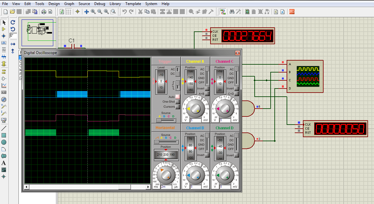
and also the output signal which I am getting is not like the one you obtained on your blog talking about SPWM;in simulation and hardware,here I am using PIC16F876A but for verification I used PIC16F877A and your code as there are but the graphs are not like yours;here I attach the graph and the simulation circuit in proteus.
can you please guide me on how I can proceed?


Thanks
 

Attachments

  • Graphs.zip
    80.6 KB · Views: 118

Re: SPWM inverter using PIC16f877A

You changed PR2 but didn't change the sine table accordingly. You also need to set the value of SET_FREQ accordingly.

Here is the corrected code:
Code:
unsigned char sin_table[64]={0, 10, 21, 31, 41, 50, 59, 68, 76, 83, 89, 
94, 99, 102, 105, 106, 107, 106, 105, 102, 99, 94, 89, 83, 76, 68, 59, 
50, 41, 31, 21, 10};


unsigned int TBL_POINTER_NEW, TBL_POINTER_OLD, TBL_POINTER_SHIFT, SET_FREQ;
unsigned int TBL_temp;
unsigned char DUTY_CYCLE;

sbit MOSA at Rb0_bit;//with PIC16F876A
sbit MOSB at Rb1_bit;//with PIC16F876A
sbit MOSC at Rb2_bit;//with PIC16F876A
sbit MOSD at Rb3_bit; //with PIC16F876A

unsigned char FlagReg;
sbit Direction at FlagReg.B0;
//0 -> MOS A + D
//1 -> MOS B + C

void interrupt(){
     if (TMR2IF_bit == 1){
        TBL_POINTER_NEW = TBL_POINTER_OLD + SET_FREQ;
        if (TBL_POINTER_NEW < TBL_POINTER_OLD){
          //CCP1CON.P1M1 =~CCP1CON.P1M1; //Reverse direction of full-bridge

           if (Direction == 0){
              MOSA = 0;
              MOSD = 0;
              MOSB = 1;
              MOSC = 1;
              Direction = 1;
           }
           else{
                MOSB = 0;
                MOSC = 0;
                MOSA = 1;
                MOSD = 1;
                Direction = 0;
           }
        }
       TBL_POINTER_SHIFT = TBL_POINTER_NEW >> 11;
       DUTY_CYCLE = TBL_POINTER_SHIFT;
       CCPR1L = sin_table[DUTY_CYCLE];
        TBL_POINTER_OLD = TBL_POINTER_NEW;
        TMR2IF_bit = 0;
     }
}
void main() {
     SET_FREQ = 468;
     PORTB = 0;
     TRISB = 0;
     PR2=107;
     CCPR1L = 0;
     CCP1CON = 12; //PWM Mode
     TRISC = 0xFF;
     TMR2IF_bit = 0;
     T2CON = 0x04; //TMR2 on
     while (TMR2IF_bit == 0);
     TMR2IF_bit = 0; //Clear TMR2IF
     PORTC = 0;
     TRISC = 0;
     TMR2IE_bit = 1;
     GIE_bit = 1;
     PEIE_bit = 1;
     while (1);
     }

Here is the output I get:

7360413900_1376717248.png


Hope this helps.
Tahmid.
 

Re: SPWM inverter using PIC16f877A

Hello,Tahmid I verified your codes in Proteus the rest is to see if my H_Bridge will run because it was a problem the msofet were becoming very hot when using that signal I found.

So can you please tell me how I get those values of sine table;the data I posted in on Post #11 are generated by your software:Smart Sine can you explain to me how to proceed?
And also when I use the formula you give for SET_FREQ calculation I get other value which is not the one you found;pleas help on those two.

Thanks
 

Re: SPWM inverter using PIC16f877A

Hello Sir here I am not getting the formula you used because,in your blog you said that:{65536/ (looktable number * number shifted)} ,but here you find 468 which formula has you applied?and also why in the look up table are you using 32 numbers while you written 64?
can you please help me to clarify on those two things?

Thanks.
 

Status
Not open for further replies.

Part and Inventory Search

Welcome to EDABoard.com

Sponsor

Back
Top