I have previously shown how to calculate the values for the sine table. Now I will show you how to use that sine table for generating a sine wave using a PIC16F684. Why PIC16F684? It is a nice little 14-pin PIC that contains all that is needed for SPWM (sinusoidal pulse width modulation) – the ECCP module. Since the ADC or comparator or other peripherals are not used and there are enough pins, I selected the PIC16F684.
You can find the tutorial here: https://tahmidmc.blogspot.com/2011/01/generation-and-implementation-of-sine.html
Let’s run the 16F684 from a 16MHz crystal oscillator and use a 16kHz switching frequency.
So, the required value of PR2 is 249.
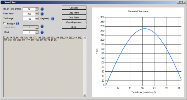
The sine table (for half a cycle) is:
0, 25, 49, 73, 96, 118, 139, 159, 177, 193, 208, 220, 231, 239, 245, 249, 250, 249, 245, 239, 231, 220, 208, 193, 177, 159, 139, 118, 96, 73, 49, 25
________________________________________________________________________________________________________________________________
Here is the code:
unsigned char sin_table[32]={0,25,49,73,96,118,137,
159,177,193,208,220,231,239,245,249,250,249,245,
239,231,220,208,193,177,159,137,118,96,73,49,25};
unsigned int TBL_POINTER_NEW, TBL_POINTER_OLD, TBL_POINTER_SHIFT, SET_FREQ;
unsigned int TBL_temp;
unsigned char DUTY_CYCLE;
void interrupt(){
if (TMR2IF_bit == 1){
TBL_POINTER_NEW = TBL_POINTER_OLD + SET_FREQ;
if (TBL_POINTER_NEW < TBL_POINTER_OLD){
CCP1CON.P1M1 = ~CCP1CON.P1M1; //Reverse direction of full-bridge
}
TBL_POINTER_SHIFT = TBL_POINTER_NEW >> 11;
DUTY_CYCLE = TBL_POINTER_SHIFT;
CCPR1L = sin_table[DUTY_CYCLE];
TBL_POINTER_OLD = TBL_POINTER_NEW;
TMR2IF_bit = 0;
}
}
void main() {
SET_FREQ = 410;
TBL_POINTER_SHIFT = 0;
TBL_POINTER_NEW = 0;
TBL_POINTER_OLD = 0;
DUTY_CYCLE = 0;
ANSEL = 0; //Disable ADC
CMCON0 = 7; //Disable Comparator
TRISC = 0x3F;
CCP1CON = 0x4C;
TMR2IF_bit = 0;
T2CON = 4; //TMR2 on, prescaler and postscaler 1:1
while (TMR2IF_bit == 0);
TMR2IF_bit = 0;
TRISC = 0;
TMR2IE_bit = 1;
GIE_bit = 1;
PEIE_bit = 1;
while(1);
}
________________________________________________________________________________________________________________________________
Download the hex file from:
https://www.4shared.com/file/PlETv7nt/SPWM684.html
https://rapidshare.com/files/3811707712/SPWM684.hex
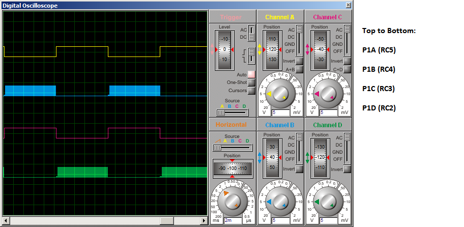
To make the process of updating sine table value simple, table pointer was used. The frequency here is set to 50Hz and the switching frequency is 16kHz. The 16F684 generates SPWM signals on P1A, P1B, P1C and P1D pins which should then be connected to a full-bridge stage for feeding into transformer.
16kHz frequency is used since it is toward the end of the audible spectrum and so the noise emitted will not be intolerable. Frequency above 20kHz is not used as 20kHz is the maximum frequency for the ECCP module of 16F684.
Since the ECCP module and interrupt take care of the SPWM, it is being executed by the hardware modules. So, while these are running, you can do other stuff as well by coding them in the while(1) loop, which, as you can see, is blank now, since no other task is being carried out besides SPWM.
Generating the sine table:
The SPWM signals:
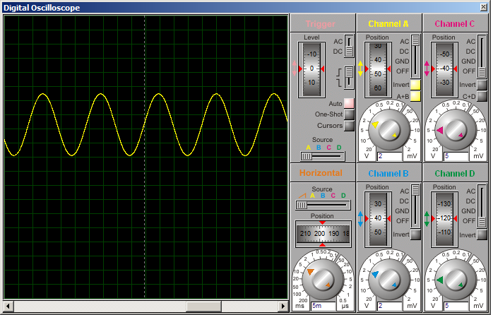
The generated sine wave:
You can find the tutorial here: https://tahmidmc.blogspot.com/2011/01/generation-and-implementation-of-sine.html
Let’s run the 16F684 from a 16MHz crystal oscillator and use a 16kHz switching frequency.
So, the required value of PR2 is 249.
The sine table (for half a cycle) is:
0, 25, 49, 73, 96, 118, 139, 159, 177, 193, 208, 220, 231, 239, 245, 249, 250, 249, 245, 239, 231, 220, 208, 193, 177, 159, 139, 118, 96, 73, 49, 25
________________________________________________________________________________________________________________________________
Here is the code:
unsigned char sin_table[32]={0,25,49,73,96,118,137,
159,177,193,208,220,231,239,245,249,250,249,245,
239,231,220,208,193,177,159,137,118,96,73,49,25};
unsigned int TBL_POINTER_NEW, TBL_POINTER_OLD, TBL_POINTER_SHIFT, SET_FREQ;
unsigned int TBL_temp;
unsigned char DUTY_CYCLE;
void interrupt(){
if (TMR2IF_bit == 1){
TBL_POINTER_NEW = TBL_POINTER_OLD + SET_FREQ;
if (TBL_POINTER_NEW < TBL_POINTER_OLD){
CCP1CON.P1M1 = ~CCP1CON.P1M1; //Reverse direction of full-bridge
}
TBL_POINTER_SHIFT = TBL_POINTER_NEW >> 11;
DUTY_CYCLE = TBL_POINTER_SHIFT;
CCPR1L = sin_table[DUTY_CYCLE];
TBL_POINTER_OLD = TBL_POINTER_NEW;
TMR2IF_bit = 0;
}
}
void main() {
SET_FREQ = 410;
TBL_POINTER_SHIFT = 0;
TBL_POINTER_NEW = 0;
TBL_POINTER_OLD = 0;
DUTY_CYCLE = 0;
ANSEL = 0; //Disable ADC
CMCON0 = 7; //Disable Comparator
TRISC = 0x3F;
CCP1CON = 0x4C;
TMR2IF_bit = 0;
T2CON = 4; //TMR2 on, prescaler and postscaler 1:1
while (TMR2IF_bit == 0);
TMR2IF_bit = 0;
TRISC = 0;
TMR2IE_bit = 1;
GIE_bit = 1;
PEIE_bit = 1;
while(1);
}
________________________________________________________________________________________________________________________________
Download the hex file from:
https://www.4shared.com/file/PlETv7nt/SPWM684.html
https://rapidshare.com/files/3811707712/SPWM684.hex
To make the process of updating sine table value simple, table pointer was used. The frequency here is set to 50Hz and the switching frequency is 16kHz. The 16F684 generates SPWM signals on P1A, P1B, P1C and P1D pins which should then be connected to a full-bridge stage for feeding into transformer.
16kHz frequency is used since it is toward the end of the audible spectrum and so the noise emitted will not be intolerable. Frequency above 20kHz is not used as 20kHz is the maximum frequency for the ECCP module of 16F684.
Since the ECCP module and interrupt take care of the SPWM, it is being executed by the hardware modules. So, while these are running, you can do other stuff as well by coding them in the while(1) loop, which, as you can see, is blank now, since no other task is being carried out besides SPWM.
Generating the sine table:
The SPWM signals:
The generated sine wave: