Continue to Site

Welcome to EDAboard.com

Welcome to our site! EDAboard.com is an international Electronics Discussion Forum focused on EDA software, circuits, schematics, books, theory, papers, asic, pld, 8051, DSP, Network, RF, Analog Design, PCB, Service Manuals... and a whole lot more! To participate you need to register. Registration is free. Click here to register now.

how to generate a broadband signal for a given bandwidth in Matlab ?

Status
Not open for further replies.

rakeshKM

Newbie level 4
Newbie level 4
Joined
Apr 15, 2013
Messages
5
Helped
0
Reputation
0
Reaction score
0
Trophy points
1,281
Visit site
Activity points
1,316
well ,I am about to design a broadband beam former. so I am curious,is it possible to create broadband signal of continuous frequency for a particular bandwidth. If no ,what is the best way to do so ?
 

If there should not be any signal parameters manipulaton, just continuous wave, then use chirp - linear FM.

- - - Updated - - -

If there should not be any signal parameters manipulaton, just continuous wave, then use chirp - linear FM.
 

well i tried this:

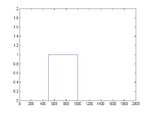
i need a broad band signal of band 500-1000 Hz
123.jpg

what i did is ...wrote code for above
and taken the idft....
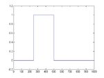
and finally find fft to check ...but i am getting this
untitled.jpg

my code is :
clc;
close all;
clear all;
t=0:0.5:1000;
for i=1:length(t)
if i>=500 & i<=1000
t(i)=1;
else t(i)=0;
end
end
f=t;
plot(f)
axis([0 2000 0 2]);
[x] = idft(f,2001);
figure
plot(0:0.5:1000,x)

figure
[Xk] = dft(x,2001)
plot(0:0.5:1000,Xk)


what is going wrong in this code ...is this approach correct
 

1. Nobody uses cycle to generate such vector.
t = [zeros(500,1); ones(500,1)];

2. I dont know where you got 'dft' function, in MATLAB there is 'fft' (and 'ifft').

3. About LFM.
For example take sample rate 4 kHz.
Assume any frequency in band 500-1000 Hz.
Taking 4 samples for 1 ms you may get the resolution of your spectra 1 kHz. (because 4 khz fs represent signal in band 2 kHz, 4 samples 2 for spectral components 0-1khz and 1-2 khz and the rest two are the same reflected). - or just 1 bin in band 0-1000.
Taking 8 samples (for 2 ms) you may improve spectrum resolution twice - with 500 Hz step.
Taking 16 samples (for 4 ms) you may improve spectrum resolution twice - with 250 Hz step. So you may detect what region your initial sime wave belong to - 500-750 or 750-1000 hz.
But you want to have 500 hz wideband signal.
So for the period of 2 ms your wave should change its frequency for that resolution - 250 Hz. In this case you will still observe the signal in band 500-1000 but not 500-750 or 750-1000 hz.
So the rate of your linear FM should be 250 Hz for 2 ms or 500 Hz per 4 ms. In band from 500 to 1000 Hz.
Something like that I think.
How to generate by means of matlab discover by yourself.
For generating this with the given sample rate 4 kHz each next sample must be of the frequency increased by (500/0.004/4000=31.25 hz) related to previous. Cyclic in band 500-1000. Clear?
 

Is there a reason you can't generate it in simulink? It may help you visualize the process before coding it in matlab.
 

thank u for ur response


i finally did it with the help of Fm modulation...i think LFm will do also fine

here is what i have done have
T=2e-6;
Fs=440e6;
Fc=120e6;
B=200e6;
ft=0:1/Fs:T-1/Fs;
N=length(ft);
k=(Fc/Fs)*2*pi/max(ft);
y=modulate(ft,Fc,Fs,'fm',k); %%band pass
y_fft=fft(y);
y1=y_fft %(1:N/2);
figure;
subplot(2,1,1);
plot(ft,y);
xlabel('t');
ylabel('y');
title('modulated output signal(t)');
subplot(2,1,2);
plot((0:Fs/N:Fs-Fs/N),abs(y_fft));
xlabel('frequency(Hz)');
title('frequency respone');
axis([-50e07 50e+07 0 50])

x=ifft(y1); %%bandpass final

figure
plot(ft,x)

j=sqrt(-1);
x1=x'*exp(-j*2*pi*120e6*ft); %% lowpass
figure
plot((-(Fs-Fs/N)/2:Fs/N:(Fs-Fs/N)/2),abs(fft(x1)))
 

Status
Not open for further replies.

Similar threads

Part and Inventory Search

Welcome to EDABoard.com

Sponsor

Back
Top