Continue to Site

Welcome to EDAboard.com

Welcome to our site! EDAboard.com is an international Electronics Discussion Forum focused on EDA software, circuits, schematics, books, theory, papers, asic, pld, 8051, DSP, Network, RF, Analog Design, PCB, Service Manuals... and a whole lot more! To participate you need to register. Registration is free. Click here to register now.

How to design Fast switching Amplifier?

Status
Not open for further replies.

020170

Full Member level 4
Joined
Jan 31, 2005
Messages
231
Helped
3
Reputation
6
Reaction score
1
Trophy points
1,298
Activity points
2,221
How to design for low ripple Amplifier?

Hello. I have a question about low switching ripple amplifier.
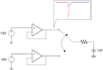
??2.png

Opamp configuration is above. two opamp outputs 13V & 10V. They loaded output capacitor 1nF. Switch period is 4us.

In switching period, switching ripple happens on the opamp output terminal. Depends on the opamp characteristics, output switching ripple maybe large, or small.

My question is below.

1. What should I concern to guarantee for low switching ripple on the opamp's output ?

2. When I design a low switching ripple output stage, what sholud I do?

Thank you
 
Last edited:

Re: How to design for low ripple Amplifier?

As the output of switch is connected to RC circuit, by increasing the time constant of RC circuit i.e. by increasing value of R or C or both can reduce the switching ripple size.
If the RC circuit is connected to another circuit with very low input impedance, it may create loading problem for the 1nF cap and the switching ripple size will be bigger both in amplitude and time. So, increasing the input impedance of circuit next to cap or increasing C or both R and C can solve the problem. The other way is to decrease switching delay to less than 1 us. Increasing the value of C also will help in reducing discontinuous noise due to change from 10V to 13V or vice versa.

Hope that helps.
 

Hi,

switching load to the output of an OPAMp will always generate a voltage ripple.

If you can´t change time constant so maybe it is possible to change load impedance. (by increasing resistor and decreasing capacitance).

The next thing is to use a high speed OPAMP so that it fastly adjusts to the changing load.

Next i´d try to use to lower the OPAMPs HF output impedance by placing an RC at the output. If the C is 1000 times as big as the load C then you max. (if not oscillating) get 1/1000 of difference_voltage ripple (=3mVp).
But this must be well calculated to ensure a stable OPAMP circuit.

It also depends on needed voltage precision. I think of a circuit with two Cs and two Rs for each OPAMP.


Klaus
 

Status
Not open for further replies.

Similar threads

Part and Inventory Search

Welcome to EDABoard.com

Sponsor

Back
Top