Continue to Site

Welcome to EDAboard.com

Welcome to our site! EDAboard.com is an international Electronics Discussion Forum focused on EDA software, circuits, schematics, books, theory, papers, asic, pld, 8051, DSP, Network, RF, Analog Design, PCB, Service Manuals... and a whole lot more! To participate you need to register. Registration is free. Click here to register now.

How to design an N channel enhancement mosfet?

Status
Not open for further replies.
hi FvM ,Barry, and all,

This few days i study the MOSFET. I think i was totally wrong in understanding the operation of a mosfet. Thank you for your guys patients on guiding me.
I am redesign some simple circuit which use p channel mosfet to work as a switched. Please have a look on the image below and do share with me your precious opinions.
Thank you very much.
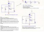
mosfet question.png
 

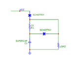
Well, you've got me totally confused. Why do you even need a switch? Connect your super cap and your load across your supply, when the supply drops, the load current is supplied from the cap. Am I missing something? Maybe you need a diode in series with the supply so the cap isn't loaded by whatever is up there, but I don't know why you need anything else.
 

Hi Barry,

The MOSFET here was a switch. When the supply voltage exits, the mosfet turn off. I (total) = I (charging ) + I (loads).
When the supply voltage was removed, the mosfet turned on and the super capacitor will become the supply voltage for the loads. I (total) = I (loads) .

The Mosfet was used to bypass the 33ohm resistor. During MOSFET was turn on, will there be any current flow into the 33ohm resistor?

Thank you
 

When the mosfet is on there will be very little current in the 33 ohm, but you still didn't answer my question: Why do you need the mosfet?

Upon further review, your circuit still won't work like you think it will. What is the voltage at the source of the mosfet? Hint: it's not zero.
 

Hi Barry,

I was trying to use the mosfet as a switch to bypass the 33ohms resistor.
During the source voltage was removed, this point become floating. Thus, i used R1 to pull down the voltage
 

Hi barry,

Thank you very much. I did considered this circuit before but it was not good enough for my implementations. Once the Vcc was removed, the super capacitor became the source voltage of the circuit. The SCHOttky diode will caused the voltage drop and my MCU will lost function in very fast time.
In my Case,
Vcc =3.6V,
Load = MCU ( min operating Voltage = 2.6 - 3V)
Thank you
 

Hi Barry ,

I increase my Vcc voltage level to compensate the voltage drop caused by the diode.

Thank you very much for your advise. It really help me a lot.
 

Status
Not open for further replies.

Similar threads

Part and Inventory Search

Welcome to EDABoard.com

Sponsor

Back
Top