Venkatlab
Junior Member level 1
**broken link removed**
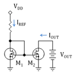
how to calculate the Resistance of M1 & M2 in saturation mode ?
What is the current though M1 & M2? Ideally it would be Iref but what would be practical case?
IRFL210--MOSFET part number
how to calculate the Resistance of M1 & M2 in saturation mode ?
What is the current though M1 & M2? Ideally it would be Iref but what would be practical case?
IRFL210--MOSFET part number
Attachments
Last edited:


